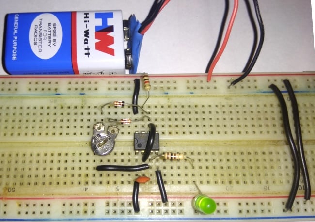
The power of a pulse-width-modulation (PWM) waveform can make or break any complex electronic circuit. From consumer-grade sound systems to vehicle engine management systems and beyond, these waveforms are essential for efficient operation. But how exactly do you generate a PWM waveform? Well, it’s not as complicated as you might think - with the right circuit diagram, you’ll be able to get one up and running in no time.
For starters, PWM circuits keep the radio frequency (RF) energy gathered from the power source intact while providing adjustable voltage control. The waveform is created by combining four distinct components: an oscillator, power switches, comparators, and timing logic. The oscillator creates a continuous signal, which is then compared against a reference voltage in the comparator. If the signal is bigger than the reference, the power switches turn on and allow current to flow. When the signal is smaller than the reference, the switches shut off and power stops flowing. The timing logic then regulates the power switches and keeps the signal within its parameters.
Using a detailed circuit diagram or software package, you can easily configure the components and create a full PWM waveform that meets your needs. The most important part of this process is knowing the proper etiquette when it comes to designing the waveform configuration. While all of the components must work together correctly, the timing and switching aspects must be adjusted in order to ensure that the desired voltage will stay steady and within its given parameters.
Designing a PWM waveform circuit doesn’t have to be daunting task. With the right knowledge and resources, you can build the perfect setup to get the job done. So why not give it a try and see what you can come up with?

555 Timer Pwm Generator Circuit Diagram

555 Timer Pwm Generator Circuit Diagram

Dds Circuit Generates Precise Pwm Waveforms Edn

Diy Circuit Design Pulse Width Modulation Pwm

555 Timer Pwm Dc Motor Sd Controller How To Mechatronics

Generation And Detection Of A Pwm Signal Electronics Post

Pwm To Analog Signal Converter Electronics Mini Project

Pulse Width Modulation An Overview Sciencedirect Topics
Can Anyone Explain The Pulse Width Modulation Circuit Using An Op Amp Quora

Circuit Of Sine Wave Generator Scientific Diagram

1hz To 150khz Pwm Frequency Generator Module

Pulse Width Modulation Pwm Circuit

Arduino Pwm Signal Generator Circuit Homemade Projects

Pwm Pulse Width Modulation For Dc Motor Sd And Led Brightness Robot Room

Activity Pulse Width Modulation Analog Devices Wiki

H Bridge Microchip Pic Microcontroller Pwm Motor Controller Ermicroblog

Basics Of Arduino Pwm Pulse Width Modulation Circuit Geeks

Pulse Width Modulator Operates At Various Levels Of Frequency And Power Analog Devices

How To Generate Pwm In 8051 Microcontroller The Engineering Projects