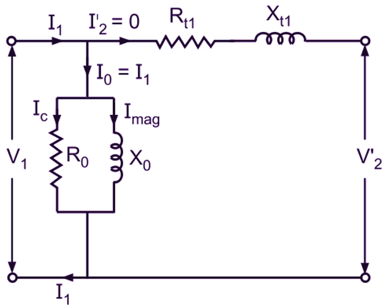
The open-test transformers circuit diagram is a useful tool for any electronics professional. It shows how different types of transformers interact with the power supply, allowing the user to troubleshoot and optimize performance.
In industrial electronics, open-end testing is a common practice, as it allows engineers to measure the input and output currents of a transformer, as well as its efficiency and other parameters. The open-test transformer circuit diagram provides a visual representation of the connections between the components and how they interact.
To understand an open-test transformer circuit diagram, one must first consider the various components involved. The primary component is the transformer itself, which is composed of two coils. The secondary coil, or secondary winding, is the coil that receives power from the primary winding. The primary winding, on the other hand, is the coil from which power is sent to the secondary winding.
In addition, there are a few other components needed for the evaluation of an open-test transformer. These include the current source, the voltage source, the load resistor, and other elements such as capacitors and inductors. These all play a role in the operation of the transformer, by providing the power and resistance necessary for evaluation.
Once all the components are understood, it’s time to draw the circuit diagram. To do this, a user starts by drawing two vertical lines representing the primary and secondary windings. From there, they add lines to represent the other components.
The open-test transformer circuit diagram is an invaluable tool for any professional working in electronics. It allows for quick, accurate measurements and diagnoses of a transformer’s performance. Understanding the components and drawing a proper diagram is key to understanding the effectiveness of a transformer. Knowing how an open-test transformer circuit is set up will give you the knowledge needed to modify or customize the transformer for better performance.

Open Circuit Test Short In Transformers

The Core Loss From Open Circuit Test Scientific Diagram

During The Open Circuit Test Of A Transformer

Transformer On No Load Condition Its Phasor Diagram Circuit Globe

Equivalent Circuit Diagram Of Single Phase Transformer Electricalunits Com

Open Circuit And Short Test On Transformer

2 4 Determine The Transformer Equivalent Circuit To Chegg Com

A Simulink Model For Open Circuit Test With B Corresponding Scientific Diagram

Transformer Simulation Perform Open And Short Circuit Tests Easily Inside Solidworks Blog

Eee 360 Energy Conversion And Transport George G

Open Delta Transformer Connection Calculation Diagram V Electrical4u
Solution Open Circuit And Short Test On Transformer Studypool

Experiment 5 Tests On A Single Phase Transformer

What Is Open Circuit Test Of Transformer Explanation Diagram Electricalworkbook

Open Circuit Test Short In Transformers

Fra Test Setup For Transformer Winding At End To Open Circuit Scientific Diagram

Open Circuit Test On Transformer Electricalvoice
Solved 1 Calculate All The Equivalent Circuit Parameters Of Chegg Com

Solved 1 Xea Using The Observation Tables For Open Circuit Chegg Com
Module And Phase Of The Open Circuit Impedance 3 Winding Test Scientific Diagram