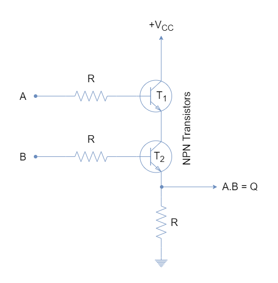
In this article, we're going to explore the remarkable world of circuit diagrams for NAND gates, specifically those using transistors. As any experienced engineer knows, the NAND gate is one of the most important and versatile logic circuits in your toolbox. The ability to control multiple inputs and outputs with a single device is a powerful asset when designing and building any electrical or electronic project.
What makes NAND gates so useful and why do so many electronics engineers rely on them? This can be answered in part by looking at the basic components of the circuit – the transistors. A transistor is a three-terminal device which is capable of amplifying a small current or voltage signal, so it can be used to control and switch larger signals. When two transistors are connected together in a certain way, they can effectively act like a switch, allowing one signal to control another signal. This is how NAND gates are constructed.
A NAND gate circuit diagram using two transistors is quite simple. It consists of two transistors connected in series, with the output of one transistor being connected to the input of the other, and the base of the first transistor connected to the collector of the second. When either input is low, it causes the output of the first transistor to go high and therefore enables the second transistor. This, in turn, causes the output of the second transistor to also go high, and this output can be used to control further logic elements.
By connecting multiple transistors together in a variety of ways, different logic functions can be created. For example, the OR gate, AND gate and NOT gate can all be created using transistors. These are all examples of digital logic, which is the basis of all modern digital circuitry.
Understanding the circuit diagram of a NAND gate using transistors can give you a much better appreciation of how digital logic works, as well as how transistors can be used in a variety of different ways. With a little creativity, you can use transistors to create many more complex logic circuits, giving you the ability to build highly sophisticated projects.

Logic Gates Using Diodes And Transitor Circuit Fever

Nor Gate What Is It Working Principle Circuit Diagram Electrical4u

Logic And Gate Electronics Lab Com

Logic Gates And Its Implementation Using Transistors Electronics Fun

Designing Or Gate Circuit Using Transistor

Nand Gate Circuit Diagram And Working Explanation

From Transistors To Gates

A Mosfet Model Of Nand Gate Tech Tips Engineering And Component Solution Forum Techforum Digi Key
Lab6 Designing Nand Nor And Xor Gates For Use To Design Full Adders

Nand Gate With 3 Inputs Truth Table And Circuit Diagram Edumir Physics

What Is A Nand Gate
How To Implement A Nand Gate Using Only Ideal Diodes Quora

Basic Logic Gates And Buffers
Xor Using Diodes Circuitlab

Simple Circuits Using Ic 7400 Nand Gates Homemade Circuit Projects

Nand Gate Transistor Logic

Digital Electronics Logic Gates Basics Tutorial Circuit Symbols Truth Tables

Activity Ttl Inverter And Nand Gate For Adalm2000 Analog Devices Wiki