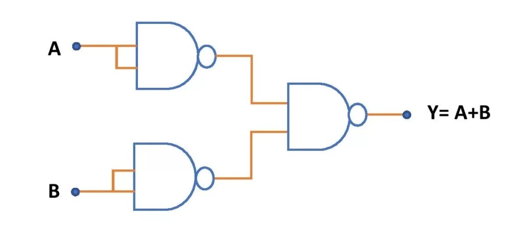
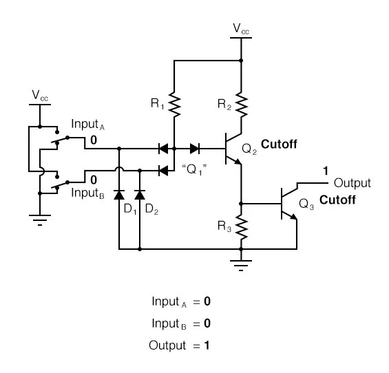
When it comes to electronics, circuit diagrams are essential to understanding how components and systems work. Circuit diagrams of NAND gates using diode can be used to understand the different electrical characteristics of such a system and to design better circuits. In this article, we'll take a look at the basics of NAND gate using diode circuit diagrams and what they can tell us.
A NAND gate is a logic gate that has two inputs and one output. When both inputs and equal, the circuit will output a zero, meaning the result is false. When either input is true and the other is false, it will output a one, meaning the result is true. To create a NAND gate circuit, a diode is required for each input. Diodes are tiny, lightweight components that control the current flow in a circuit, allowing it to be switched on or off depending on the voltage being applied.
When looking at a circuit diagram of NAND gate using diode, you will notice the two diodes which are connected to the inputs. When a positive voltage is applied to the first input, it will result in a negative charge on the second diode, and vice versa. The third component is the output, which is connected to the NAND gate. As the inputs change, the output will switch between 0 and 1 based on the logic of the circuit.
The use of diodes in NAND gates can provide greater flexibility in designing circuits, as the output of the gate can now switch between 0 and 1 based on the voltage being applied. This type of circuit can be used in a variety of applications from controlling motors to creating digital logic gates. By understanding the circuit diagram, you can build circuits with greater accuracy and efficiency.
Overall, circuit diagrams of NAND gate using diode can provide a wealth of information about the properties of such a circuit. By learning to read these diagrams, you can gain a better understanding of how these circuits work and design your own with more precision.

74ls00 Pinout Configuration Equivalent Circuit Datasheet

Ttl Totem Pole Nand Gate Logic Circuit Design Educative Site

Institut Observator Jucăuş Not Gate Using Diode And Led Vegi Nto Net
How Does A Nand Gate Work In Regards To Transistors Can It Be Create Any Other Quora

Not Gate How Does It Work Circuit Diagram Working Principle Electrical4u

Transistor Logic Ttl Page 1 Of 2

Diode Transistor Logic Dtl

Diode Transistor Logic Dtl

Nand Gate Using Diode Circuit

Diode And Transistor Nand Gate Or Dtl Ics Electrical4u
1 Design A Three Input Nand Gate Using Diode Logic And Transistor Inverter

Not And Or Gate Using Nand Circuit Diagram Edumir Physics

Transistor Logic History Types Working Its Applications

Ttl Nand And Gates Logic Electronics Textbook

Basic Logic Gates With Truth Tables Digital Circuits

Nand Gate Truth Table Circuit Design Applications And Advantages

Mcatutorials Com Combinational Circuits

Schmitt Trigger Based Nand Gate Scientific Diagram
Xor Using Diodes Circuitlab