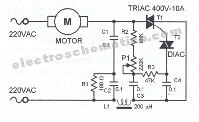
If you’re looking to upgrade your motor controller, understanding the circuit diagram of a motor controller is essential. A circuit diagram of a motor controller uses symbols to show the connection between components. It helps to understand how the components interact with one another. Knowing what each component does and how it connects to other components will help you choose the best motor controller for your application.
Understanding the circuit diagram of a motor controller is especially important if you are making modifications or repairs to your motor controller. By studying the circuit diagram, you can identify which wires connect to which components, as well as how the circuit interacts with other components. This knowledge can be invaluable when you are troubleshooting or attempting to repair your motor controller.
The first thing you should do when examining a circuit diagram is familiarize yourself with the symbols used to represent components. A few standard symbols are used in almost all motor control circuits, such as resistors, capacitors, and transistors. Once you understand the symbols used, you can easily identify the component locations and determine how they are connected.
Next, take a look at the power supply and connection points. Identify the voltage and current draw of each component, and make sure that the power supply can handle these requirements. You also want to check the power ratings of the switches and connections on the controller, as these are another common source of problems.
Finally, make sure you understand how the various components on the circuit diagram work together. Pay close attention to how the switches and relays interact with the controller, as these are often the most important elements. Once you understand the circuit, you can use this information to reproduce or modify your circuit as needed.
By understanding the circuit diagram of a motor controller, you can make informed decisions about upgrades or repairs to your motor controller. This can save you time and money in the long run, as well as ensuring that your motor controller works properly. With this knowledge, you can confidently make modifications and repairs to your motor controller.

Basic Circuit Diagram For The Bldc Motor Control System Scientific

Forward Reverse Dc Motor Control Diagram With Timer Ic

Simplifying Bldc Motor Control Design Renesas

Dc Motor Sd Controller Electronic Schematic Diagram

Ac Motor Control Circuits Worksheet Electric

Three Phase Six Step Motor Control Circuit Diagram Composed Of Mc33035 Under Stepper Circuits 60609 Next Gr

Circuit Diagram Of The Constant Sd Dc Motor Driver D In Figure 4 Scientific

The Schematic Diagram Of Motor Controller Board Is Shown In Scientific
Motor Control Circuitlab

Low Voltage Dc Motor Sd Control Circuit

Motor Control Circuits Types Electrical Automation Plc Programming Scada Pid System

Ac Motor Sd Controller Circuit

Motor Circuits And Control Applied Electricity

Igbt 10a Pwm 230v Motor Sd Control Circuit Electronics Projects Circuits
Registered Master Electricians Of The Philippines Motor Control Language Electrical Symbols Words And Line Diagrams Provide Information Necessary To Understand Operation Circuits Together They Create

Stepper Motor Controller Using Tda2030 Electronic Schematic Diagram

3 Simple Dc Motor Sd Controller Circuits Explained

Drafting For Electronics Motors And Control Circuits Part 2

Ac Motor Sd Control Circuit Hobby Circuits Soldering Mind

Sensored Brushless Dc Bldc Motor Control With Pic16f877a
