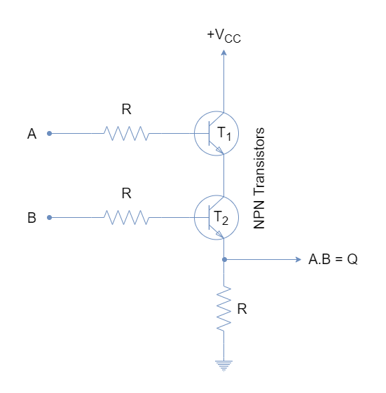
Circuit diagrams of logic gates are an essential skill for any aspiring electrical engineer. These diagrams are used to control the flow of electricity in a system, helping to optimize processes and create more efficient systems. In this article, we will discuss the basics of circuit diagrams using integrated circuits (ICs).
Integrated circuits (ICs) are electronic components that can be found in almost all kinds of electronics. They are small pieces of silicon-based technology that contain a wide variety of specialized components. Integrated circuits are often used as building blocks in creating larger, more complex electrical systems such as computers or machines. Building circuit diagrams of logic gates using ICs is a fundamental step in designing electronic systems.
When designing a logic gate system with ICs, the layout of the circuit is very important. The ideal circuit layout should have clear lines of communication between the various components and account for the flow of electricity as it goes around the circuit. Careful planning is essential to ensure that the entire system will function properly.
It is also important to consider the timing of the circuit, as this will affect how quickly the signals move around the system. Timing can be controlled by the addition of capacitors, resistors, and transistors to the circuit. After the circuit is laid out, the individual components must be connected in the correct order, ensuring that the system works as expected.
Finally, the integrated circuit-based logic gate system must be tested to verify that it works properly. As the system is tested, different inputs are applied to it and the outputs are observed. The testing process checks to see if the IC system is delivering the desired output for each input.
Learning how to design and build circuit diagrams of logic gates using integrated circuits is a valuable asset for any electrical engineer. It requires the ability to understand electrical systems, plan out the timing of the circuit, lay out the connections, and most importantly, test the system to make sure it works correctly. With the right training and practice, anyone can learn the necessary steps to build their own IC-based logic gates.

Experiment 1 Basic Logic Gates

Simple Combination Lock Digital Integrated Circuits Electronics Textbook

Breadboard 2 Logic Multiple Gates Joe S Hobby Electronics

B Digital Electronics Integrated Circuit Logic Gates Article Dummies

Digital Integrated Circuits An Overview Sciencedirect Topics

Or Gate Circuit Diagram Using Ic 74ls32

Basic Logic Gates

What Are Logic Gates Or And Not Gate With Truth Table Electronics Coach
Laboratory Manual Digital Systems And Logic Design

Logic And Gate Electronics Lab Com

Sub Kbt Micro Electromechanical Irreversible Logic Gate Nature Communications

Cs 250 Lab 1
Lab Manual Digital Electronics Amittal

Logic Gate Types Including Circuit Diagram Symbols And Uses

Cell Phone Controlled Land Rover Using Logic Gates

Logic Gates And Gate Or Nor Nand Truth Table

Understanding Digital Buffer Gate And Logic Ic Circuits Part 1 Nuts Volts Magazine

On Off Scr Control Circuit With Logic Gate Ic Eleccircuit Com