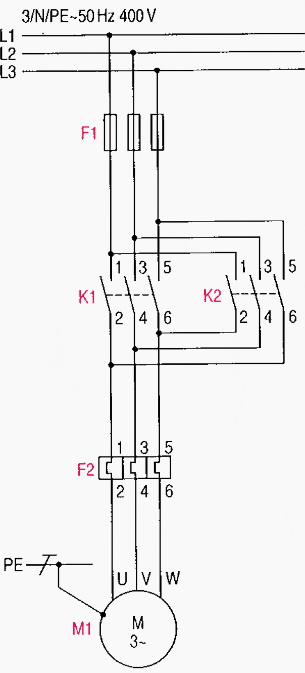
When running a large scale manufacturing operation, control systems play a crucial role. Circuit diagrams of control systems using contactors can provide the necessary information for engineers and technicians to accurately manage operations.
A contactor is an electrically controlled switch used in automation systems. It can be used to control operations such as starting and stopping motors, controlling temperature and pressure, and other processes. The circuit diagram of these systems requires familiarity with electrical engineering principles.
Creating a circuit diagram of control systems using contactors begins with understanding the basic components that make up the system. These include the contactors themselves, which are the heart of the system. They are normally rated by voltage and current, based on the load they need to handle. Additionally, other components such as relays, switches, and timers are needed to trigger contactors to start or stop the motors or other operations.
Once the components have been identified, the next step is to draw the actual wiring diagram. This includes connecting the contactor’s power lines and wires to the terminals of the motor, transformer, and other devices. Additionally, the wiring must be properly insulated in order to prevent short circuits or sparks from occurring.
Finally, once the wiring is complete, mechanical contactors need to be installed. This involves mounting the contactors on the frame of the system and connecting them to the actuators, which are responsible for controlling the motor’s speed and direction.
Circuit diagrams of control systems using contactors can be a complex process, but with the right fundamentals, they can be created with accuracy and ease. It’s important to note that the system must be thoroughly tested and inspected before it goes into operation, as any errors might cause costly downtime. By understanding and following the correct steps, it’s possible to create reliable and efficient control systems for any industrial application.

Begin To Learn Electrical Control Systems How

Motor Control Circuit Wiring Inst Tools

Relay Logic Elevator Plc And Circuit Diagram

Grid Mains To Generator Changeover Relay Circuit Homemade Projects

Main And Auxiliary Circuit Diagrams Of Switching Three Phase Motors Via Contactor Directly Eep

Motor Control Circuits Types Electrical Automation Plc Programming Scada Pid System

P0ae6 225

Motor Control Circuit Wiring Inst Tools

Contactor Overload Maintained Switch Wiring For Magnetic Motor

Contactors And Relays Construction Operation

Sequential Logic Control In Plc Engineers Community

Circuit Diagram Of The Control System Scientific

Start Stop Circuit What They Are Where And How To Wire

Circuit Diagram Of Water Pump Control System Scientific

Circuit Diagram Of The Automatic Changeover Switch With Timer Scientific

Main And Auxiliary Circuit Diagrams Of Switching Three Phase Motors Via Contactor Directly Eep

Main And Auxiliary Circuit Diagrams Of Switching Three Phase Motors Via Contactor Directly Eep

Two Wire Control Start Stop Jog Circuit