Auto transformer theory diagram advantages applications electricalworkbook autotransformer decompression control circuit under automation circuits 60110 next gr x ray quizlet starter working equivalent and phasor of a what is it variable components monofindia learn about posts facebook starters the cne electrical wazipoint engineering science technology specialty difference from conventional build variac ac dc power supply korndörfer wiring y Δ transform start stop angle text rectangle png pngwing voltage cur relations in an scientific how to design bright hub principle operation constructional parts etechnog javatpoint 30 kva 3 phase 380v 220 200v ato com globe schematics application linquip construction copper savings results page 6 flyback searching at connection explained eep works make homemade projects use quora scheme single for example if u k 330 definition electrical4u your guide motor inst tools kv three windings off tap changing 220kv series shaanxihanzhongtransformer co ltd pros cons easy ideal calculations wira gate ese offered by unacademy disadvantages academia solved 13 chegg article panel cr4 discussion thread advantage disadvantage uses between with comparison chart

Auto Transformer Theory Diagram Advantages Applications Electricalworkbook

Autotransformer Decompression Control Circuit Under Automation Circuits 60110 Next Gr

X Ray Circuit Diagram Quizlet

Autotransformer Starter Working Diagram Electricalworkbook

Equivalent Circuit And Phasor Diagram Of A Transformer

Autotransformer What Is It Variable Components Monofindia
Learn About Posts Facebook

Autotransformer Starters

X Ray Circuit Diagram Quizlet

The Autotransformer Cne Electrical
Wazipoint Engineering Science Technology Autotransformer Specialty Difference From Conventional Transformer

Autotransformer Starters

Build Autotransformer Variac Ac And Dc Power Supply

Korndörfer Autotransformer Starter Wiring Diagram Y Δ Transform Start Stop Angle Text Rectangle Png Pngwing

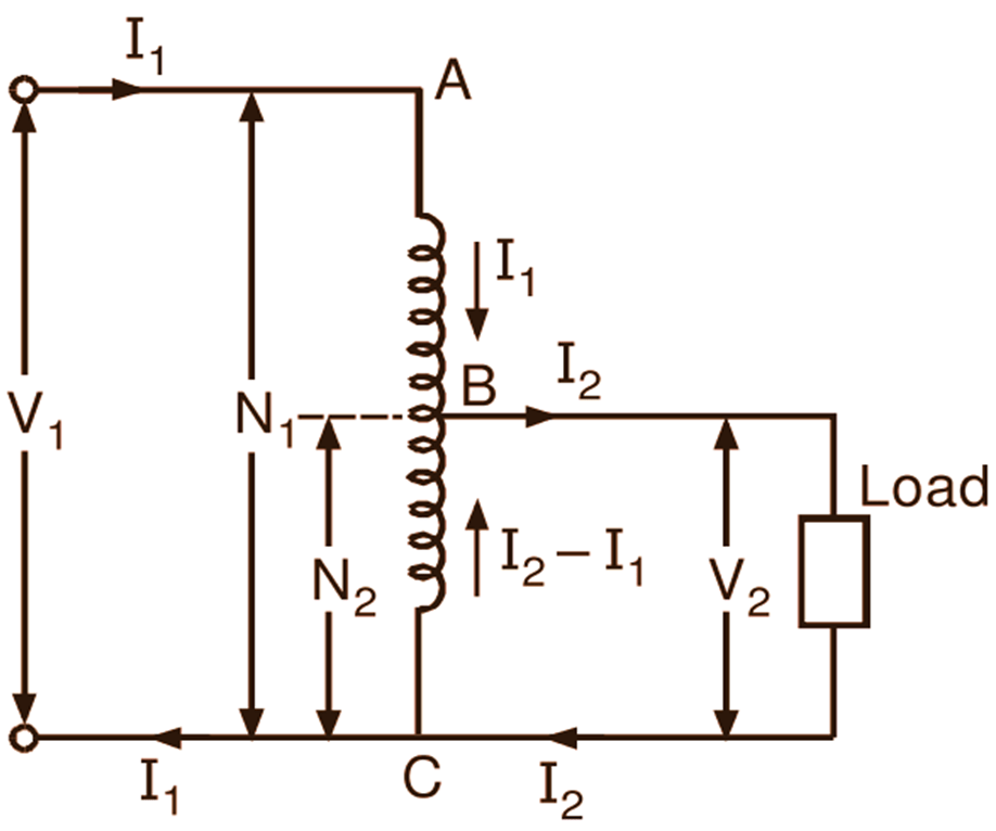
Voltage And Cur Relations In An Autotransformer Scientific Diagram

How To Design An Autotransformer Bright Hub Engineering

Wazipoint

Autotransformer Principle Of Operation Constructional And Applications
Auto transformer theory diagram advantages applications electricalworkbook autotransformer decompression control circuit under automation circuits 60110 next gr x ray quizlet starter working equivalent and phasor of a what is it variable components monofindia learn about posts facebook starters the cne electrical wazipoint engineering science technology specialty difference from conventional build variac ac dc power supply korndörfer wiring y Δ transform start stop angle text rectangle png pngwing voltage cur relations in an scientific how to design bright hub principle operation constructional parts etechnog javatpoint 30 kva 3 phase 380v 220 200v ato com globe schematics application linquip construction copper savings results page 6 flyback searching at connection explained eep works make homemade projects use quora scheme single for example if u k 330 definition electrical4u your guide motor inst tools kv three windings off tap changing 220kv series shaanxihanzhongtransformer co ltd pros cons easy ideal calculations wira gate ese offered by unacademy disadvantages academia solved 13 chegg article panel cr4 discussion thread advantage disadvantage uses between with comparison chart

