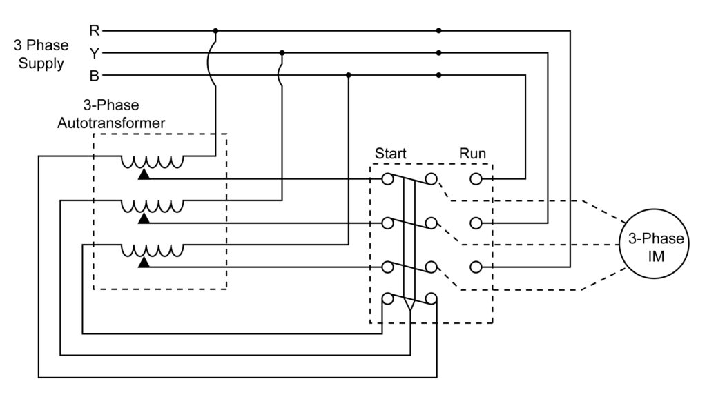
Circuit Diagram Of Autotransformer Starter
Autotransformer starters are a type of reduced voltage starter used with squirrel cage induction motors. They use an autotransformer to reduce the line voltage to the motor, thus eliminating the need for a large contactor and manual switches. The use of an autotransformer starter is especially useful in applications where there is limited space or high inrush currents.
A typical circuit diagram of an autotransformer starter includes components such as motor starters, autotransformers, contactors, thermal overloads, and grounding panels. The motor starters are used to reduce the high voltage while the autotransformer is used to slowly reduce the voltage down to the operating voltage of the motor. Contactors are electrically operated switches that are controlled by the motor starters. Thermal overloads protect against the motor overheating, while grounding panels ensure the electrical safety of the circuit.
The advantages of using an autotransformer starter include simplified installation, lower cost, and improved safety. The wiring connections are much simpler than traditional reduced voltage starters, as fewer components are required. Additionally, the autotransformer reduces the starting current, thus decreasing the load on the power supply. This can help prevent voltage drops and damage to the motor or other equipment. Finally, all the control elements are housed in one unit, meaning there is less risk of operator error and accidental contact with live parts.
In summary, autotransformer starters provide a safe and cost-effective method of starting motors with reduced voltage. With fewer components to install and maintain, they are a great choice for applications where space and energy efficiency are a priority. In addition, their self-contained design ensures safe operation, meaning you can be confident your motor will start reliably and efficiently every time.

Schematic Of The Power Circuit Electro Pump Starter Via Automatic Scientific Diagram
Autotransformer Starter Diagram Parts Working Principle Etechnog

Reduced Voltage Motor Starters Electrical Academia

Autotransformer Starter Working Principle Pros Cons Applications

Starting Motor With Auto Transformer

What Are Diffe Types Of Motor Starting Methods

Auto Transformer Starter Panel Cr4 Discussion Thread

Techtopics No 133 Siemens Usa

Autotransformer Starters

Autotransformer Starter A Reduced Voltage Motor Starting Method Disturbance

Dol Starter Direct Online Wiring Diagram Working Principle Electrical4u

Induction Motor Starter Types Circuit Diagram

Energies Free Full Text Comparative Analysis Of 18 Pulse Autotransformer Rectifier Unit Topologies With Intrinsic Harmonic Cur Cancellation Html

Electrical Motor Starter Circuits Inst Tools

Auto Transformer Starter Scientific Diagram

Autotransformer Starter A Reduced Voltage Motor Starting Method Disturbance

Starting Method Bartleby

Autotransformer Starters

Autotransformer What Is It Definition Theory Diagram Electrical4u
