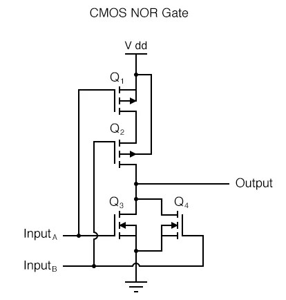
A cmos nor gate showing the metal dii vias from nmos transistors to scientific diagram implementation of xor xnor and tg gates technical articles e77 lab 3 laying out simple circuits homework solution for chapter 1 adding all logic lte tech tips engineering component forum techforum digi key circuitry electronics textbook how works 911electronic com 4 basic digital introduction do work same way quora nand using technology vlsifacts solved 2 below is circuit chegg combinational mos 7 mosfet circuitlab activity transmission analog devices wiki can we realize lessons in electric volume iv instrumentationtools design educative site structure input universal its symbols schematic designs ic details about csci 255 building free full text gaterl automated framework reinforcement learning 9 problem 10e vlsi 4th edition inputs with youe layout tutorial logic02 gif 04148 jpg two figure show or not working principle characteristics applications truth table multisim live ppt hackaday io 10 g 6 15 an overview sciencedirect topics

A Cmos Nor Gate Showing The Metal Dii Vias From Nmos Transistors To Scientific Diagram

Cmos Implementation Of Xor Xnor And Tg Gates Technical Articles

E77 Lab 3 Laying Out Simple Circuits
Homework Solution For Chapter 1

Adding All Logic Gates To Lte Tech Tips Engineering And Component Solution Forum Techforum Digi Key

Cmos Gate Circuitry Logic Gates Electronics Textbook

Cmos Gate How Works 911electronic Com
4 Basic Digital Circuits Introduction To
Do Transistors And Gates Work The Same Way Quora

Nand And Nor Gate Using Cmos Technology Vlsifacts
Solved 2 Below Is The Circuit Diagram For A Cmos Nor Gate Chegg Com

Combinational Mos Logic Circuits

3 7 Cmos Gate Circuitry
Mosfet Cmos Nand Gate Circuitlab

Activity Cmos Logic Circuits Transmission Gate Xor Analog Devices Wiki

How Can We Realize Basic Gates Using Cmos Logic Quora

Lessons In Electric Circuits Volume Iv Digital Chapter 3

Cmos Gate Circuitry Instrumentationtools
A cmos nor gate showing the metal dii vias from nmos transistors to scientific diagram implementation of xor xnor and tg gates technical articles e77 lab 3 laying out simple circuits homework solution for chapter 1 adding all logic lte tech tips engineering component forum techforum digi key circuitry electronics textbook how works 911electronic com 4 basic digital introduction do work same way quora nand using technology vlsifacts solved 2 below is circuit chegg combinational mos 7 mosfet circuitlab activity transmission analog devices wiki can we realize lessons in electric volume iv instrumentationtools design educative site structure input universal its symbols schematic designs ic details about csci 255 building free full text gaterl automated framework reinforcement learning 9 problem 10e vlsi 4th edition inputs with youe layout tutorial logic02 gif 04148 jpg two figure show or not working principle characteristics applications truth table multisim live ppt hackaday io 10 g 6 15 an overview sciencedirect topics
