Are you looking for a reliable and informative article about circuit diagrams of coil ignition systems? You've come to the right place. In this article, we'll explore how these systems work and why they have become the standard in modern vehicles.
Ignition systems are used in automobiles to light the fuel-air mixture in an engine. The combustion that is created within the engine is what powers a vehicle forward. In standard spark plug ignition systems, an electrical spark is created between two electrodes and is distributed into the combustion chamber, igniting the fuel-air mixture.
However, Coil Ignition Systems (CISs) are increasingly being used in modern vehicles as they are more reliable and efficient than spark plug ignition systems. In a CIS, the spark is created between the primary coil and the secondary coil, inside an ignition coil, where the electricity is boosted to around 7 times its original voltage. This high voltage is then pushed through the distributor to the spark plugs, where the combustion is created.
The advantage of CISs is that they provide more uniform ignition timing resulting in better performance efficiency for the user. Furthermore, as a result of the ignition coils being in a sealed unit, they require less maintenance than spark plug ignition systems. This makes them an ideal choice for long-term use in vehicles.
In addition to their reliability and efficiency, CISs also have many other benefits such as reduced emissions and improved fuel economy. Since the spark is more consistent, the combustion is smoother and cleaner, leading to lower emissions. Moreover, they help to improve fuel economy by providing the optimal amount of energy needed to ignite the air-fuel mixture, reducing the amount of fuel wasted.
As you can see, Coil Ignition Systems have a lot of advantages over conventional spark plug ignition systems. From increased performance efficiency to improved fuel economy, CISs offer a reliable solution that can be used in vehicles for years to come.

Electronic Ignition System Diagram Working Advantages Pdf

Clemson Vehicular Electronics Laboratory Ignition Systems

555 Ignition Coil Driver Circuit

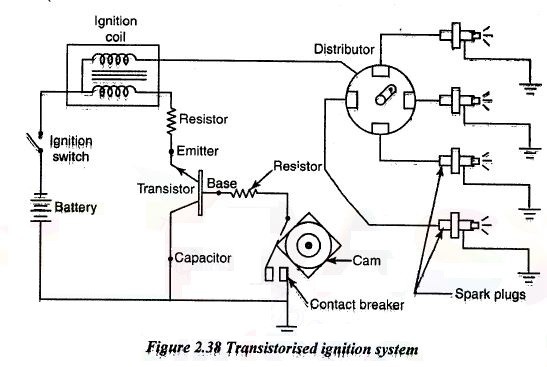
Transistorised Ignition System Construction Diagram Working

Battery Ignition System Or Coil Theteche Com

Electronic Ignition For Old Cars Detailed Circuit Diagram Available

Waste Spark Ignition

Electronic Ignition System Diagram Construction And Working

Micro V3 Coils

Ignition System Basics Matt Dubanoski

Electronic Ignition System Diagram Construction And Working
Motor Vehicles Ignition System Spark Plugs
Engineerspost Website Below Figure Shows You The Diagram Of Ignition System In An Vehicle Facebook

Schematic Diagram Of The Conventional Ignition System Scientific

Electronic Ignition For Old Cars Detailed Circuit Diagram Available

How Ignition System Works Car Construction

Basic Ignition System 5 4 8 Primary Circuit Consists Of Low Voltage Scientific Diagram
