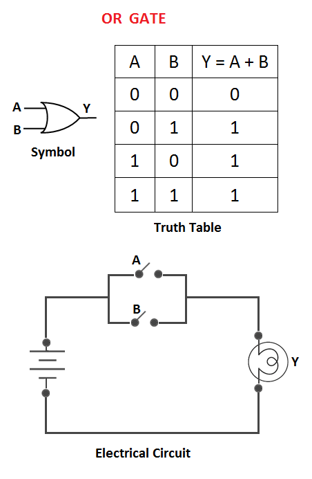
When it comes to modern electronics, circuit diagrams are essential for understanding how their components work together. As a result, the ability to understand circuit diagrams has become an important skill for engineers and tech-savvy hobbyists alike. In this blog, we will explore one of the most fundamental circuit diagrams out there: the AND gate circuit diagram.
AND gates are widely used in digital circuits because of their simplicity and versatility. The AND gate is a two-input logic gate that uses a control signal to turn two inputs into one output. Put simply, the AND gate requires both inputs to be present in order to produce its output.
To illustrate how this works, let’s look at a simple AND gate circuit diagram. In the diagram, you can see two inputs A and B connected to the AND gate symbol. If both inputs A and B are ‘HIGH’, the output of the AND gate is also ‘HIGH’. However, if either input A or B is ‘LOW’, then no output is produced.
Understanding an AND gate circuit diagram is useful for designing many types of digital circuits. It’s often used in combination with other logic gates such as OR, NOR, and XOR to create sophisticated electronic designs. It can also be used to create circuits that perform actions based on specific combinations of inputs, such as a security system that only unlocks if two different buttons are pressed.
In summary, the AND gate circuit diagram is an essential tool for anyone who wants to understand how digital circuits work. By understanding the basic principles behind the AND gate, you can start designing complex digital systems that make use of multiple inputs to generate a single output.

And Gate Transistor Level Schematic Scientific Diagram
Lab6 Designing Nand Nor And Xor Gates For Use To Design Full Adders

Multiple Input Gates Logic Electronics Textbook
How Would You Draw The Logic Circuit Using Gates For Sop Expression Ab Bcd Ac Quora

Logic Gate Types Including Circuit Diagram Symbols And Uses

The Diagram Of Logic Gate Circuit Is Given Below Class 12 Physics Cbse

Cmos Nand Gate Circuit Diagram Working Principle Truth Table
Can I Build A Nand Gate Using Only Diodes And Resistance Quora

What Is A Not Gate Logic Symbol Truth Table Circuit Globe

Digital Electronics Logic Gates Basics Tutorial Circuit Symbols Truth Tables
Electronics Circuit Diagram Circuitspedia Nand Gate Facebook

Logic Gates Using Diodes And Transitor Circuit Fever

And Gate Circuit Diagram Working Explanation

Truth Tables Circuit Diagrams Of Logic Gates Your Electrical Guide

Truth Tables Circuit Diagrams Of Logic Gates Your Electrical Guide

Schematic And Logic Diagrams

Digital Electronics Logic Gates Basics Tutorial Circuit Symbols Truth Tables

Basic Logic Gates

Logic Gates

Truth Tables Circuit Diagrams Of Logic Gates Your Electrical Guide
