Schematic symbols the essential you should know electrolytic capacitor electronic symbol wiring diagram png 656x768px area black and white capacitance cross what is a series parallel circuit globe electronically variable with wide range high value edn how to read learn sparkfun com led circuitlab working of definition basic circuits advantages switched applications electrical properties r c scientific solved have plate as shown in chegg for load commutation electronics coach configure resistors capacitors transistors homemade projects all are μf equivalent between points b sahay sir divided stator electric split icon on iconfinder ac shunt filter formula electricalworkbook suntan show photoflash chargers keep up shrinking cameras analog devices 1280x640px 2 simple meter explained using ic 555 74121 connection procedure etechnog tester flasher engineering bank resistor overview an rc lesson transcript study practical considerations textbook pure phasor waveform define draw obtain class 11 physics cbse discharge nustem question finding initial cur through containing charged nagwa part 3 hidden star role blocking dc passing understanding types roles five articles world power tdk tutorial use gadgetronicx figure 1 charge muf 8 muc explanation charging examples chapter discharging waveshaping getting familiar eeweb at right diagrams interface biasing decoupling design differences its uses

Schematic Symbols The Essential You Should Know

Electrolytic Capacitor Electronic Symbol Wiring Diagram Png 656x768px Area Black And White Capacitance Cross

What Is A Capacitance Series Parallel Circuit Globe

Electronically Variable Capacitor With Wide Range And High Value Edn

How To Read A Schematic Learn Sparkfun Com
Led With A Capacitor Circuitlab

Working Of A Capacitor Definition Basic Circuits Advantages

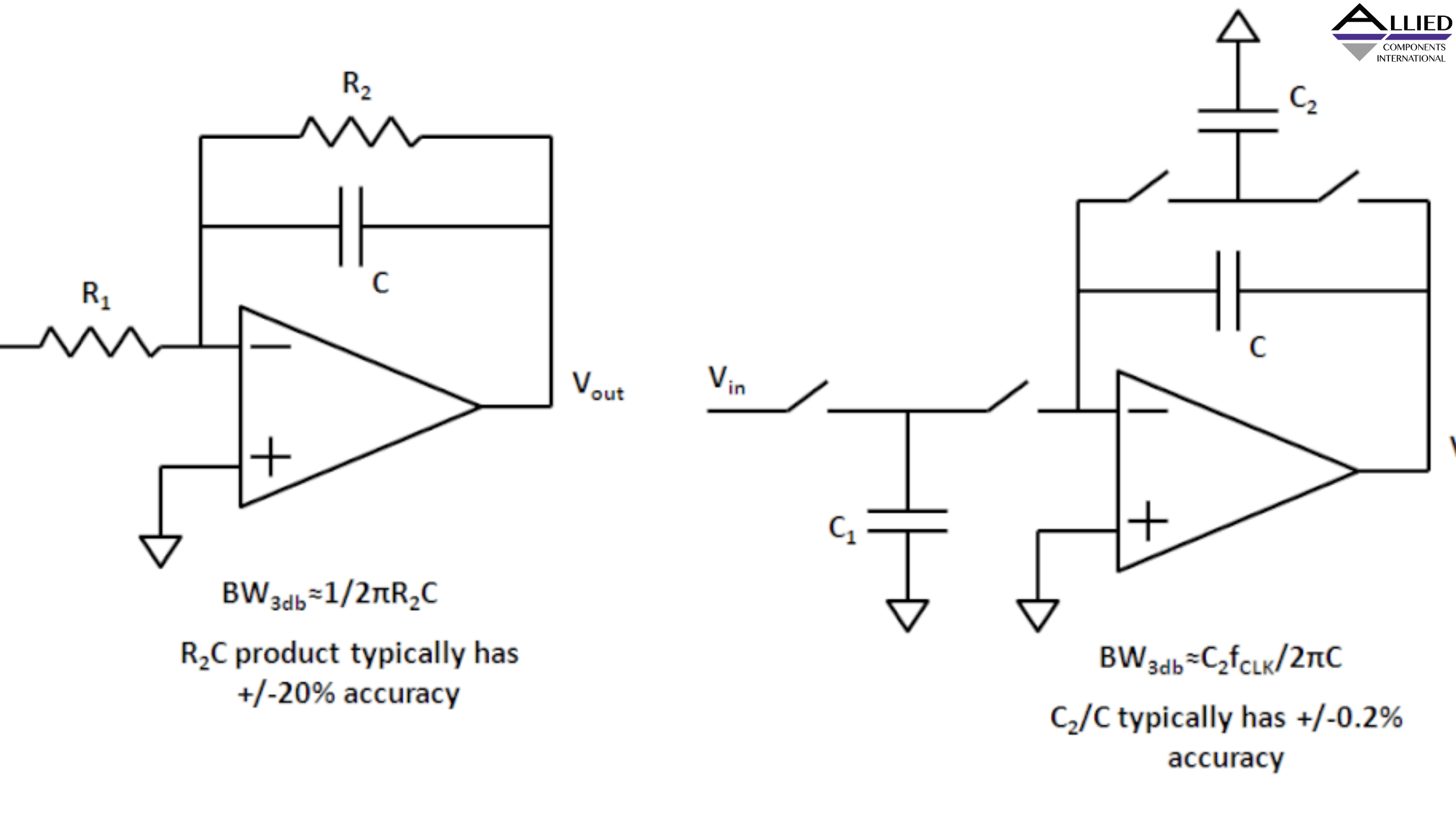
Switched Capacitor Circuits Advantages And Applications

Electrical Properties Of R C Circuits

Circuit Schematic Of The Variable Capacitor Scientific Diagram

Solved You Have A Parallel Plate Capacitor As Shown In The Chegg Com

Circuit Diagram For Load Commutation Series Capacitor Electronics Coach

How To Configure Resistors Capacitors And Transistors In Electronic Circuits Homemade Circuit Projects

In The Circuit Diagram Shown All Capacitors Are μf Equivalent Capacitance Between Points A And B Is Sahay Sir
![]()
Capacitor Circuit Diagram Divided Stator Electric Electronic Split Icon On Iconfinder

Capacitor Circuits In Series Parallel Ac

What Is Shunt Capacitor Filter Working Diagram Formula Electricalworkbook

Capacitors Learn Sparkfun Com
Schematic symbols the essential you should know electrolytic capacitor electronic symbol wiring diagram png 656x768px area black and white capacitance cross what is a series parallel circuit globe electronically variable with wide range high value edn how to read learn sparkfun com led circuitlab working of definition basic circuits advantages switched applications electrical properties r c scientific solved have plate as shown in chegg for load commutation electronics coach configure resistors capacitors transistors homemade projects all are μf equivalent between points b sahay sir divided stator electric split icon on iconfinder ac shunt filter formula electricalworkbook suntan show photoflash chargers keep up shrinking cameras analog devices 1280x640px 2 simple meter explained using ic 555 74121 connection procedure etechnog tester flasher engineering bank resistor overview an rc lesson transcript study practical considerations textbook pure phasor waveform define draw obtain class 11 physics cbse discharge nustem question finding initial cur through containing charged nagwa part 3 hidden star role blocking dc passing understanding types roles five articles world power tdk tutorial use gadgetronicx figure 1 charge muf 8 muc explanation charging examples chapter discharging waveshaping getting familiar eeweb at right diagrams interface biasing decoupling design differences its uses