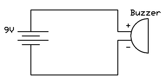
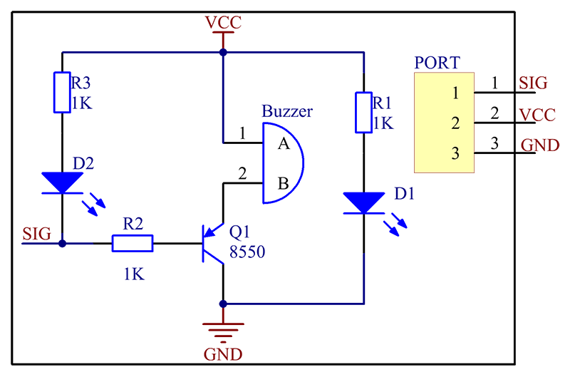
Electronic buzzers are a common and reliable way to generate alerts in many different applications. This includes everything from warning alarms in cars to doorbells in homes. But how do these devices work? A key component is the buzzer circuit, which is responsible for generating an audible signal. In this article, we'll look at the workings of one such circuit - the basic buzzer circuit diagram.
The buzzer circuit is simple and straightforward. It consists of a few basic components – a voltage source, a transistor, an inductor, and a diode. When the voltage is applied, the transistor switches on, which then causes current to flow through the inductor. This creates a magnetic field which induces current to the diode. The diode then converts this current into an audible sound by vibrating. The resulting sound can be quite loud depending on the design of the circuit.
Buzzer circuits are used in many different applications. This includes industrial machinery, home security systems, and consumer electronics (such as toys). They can also be used in medical equipment, where an alarm may be required to alert staff of a particular condition. In fact, you’ll probably find a buzzer circuit hidden away inside almost any piece of electronic equipment.
The great thing about buzzer circuits is that they’re relatively easy to build. All you need is a few basic components and some basic knowledge of electronics. It’s also possible to modify existing designs to suit specific needs. For example, you can increase or decrease the power output, or even adjust the frequency of the buzzer.
Overall, the buzzer circuit diagram is a reliable and easy way to generate an audible signal. With some basic knowledge, it’s possible to create your own buzzer circuits to meet a variety of needs. Buzzer circuits are versatile and can be used in almost any electronic project. So if you’re looking to add a little extra noise to your next project, consider using a buzzer circuit.

Buzzer With Incrementing Beep Rate Homemade Circuit Projects

Simple Buzzer Circuit With Ne555 Ic
Arduino Ir Sensor And Buzzer Circuit Scientific Diagram
Question Regarding Buzzer Circuit All About Circuits

Magnetic And Piezo Buzzer Circuits

Circuit Diagram Of Buzzer Connection Scientific

Remote Controlled Alarm Circuit

How To Interface Piezoelectric Buzzer With Arduino Makerguides Com

How To Build A Buzzer Circuit

3 Temperature Detector Circuit With Buzzer Alarm Eleccircuit Com

Esp32 On Piezo Buzzer Tutorial

The Sunrise Wake Up Alarm Build Electronic Circuits
Buzzer Circuit How To Create And Enhance An Easy Design

Buzzer Modules Wiki

Novel Buzzer Circuit Diagram Project Alarms Security Related Schematics And Tutorials Electronics Hobby Projects

Diy Piezo Speaker Hot 59 Off Www Ingeniovirtual Com