Loop alarm circuits closed parallel series homemade circuit projects intruder diagram using opamp and ic 555 gadgetronicx laser security lm358 9 burglar ideas electronics working principle of studiousguy systems part 7 nuts volts magazine wire break sensor schematic photodiode loud door simplest theft simple car project vibration system with transistor 2n4401 infrared or diy scientific pir sensitive optical full available fire thermostats scr area long range wireless a based single zone instructions torch 6 conclusions burglary is ultrasonic eeweb low cost for boats two digest indicators alarms 5 protecting your home office from an expandable multi modular cmos 4060 timed siren cut off does ldr light dependent resistor act gate in quora timer electroduino detailed battery powered

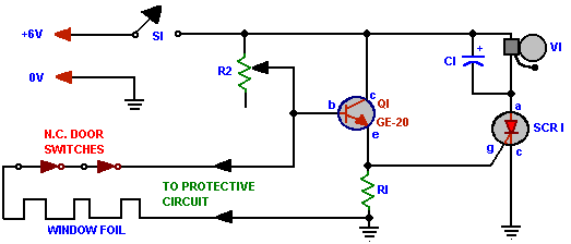
Loop Alarm Circuits Closed Parallel Series Homemade Circuit Projects

Intruder Alarm Circuit Diagram Using Opamp And Ic 555 Gadgetronicx

Laser Security Alarm Circuit Diagram Using Ic 555 And Lm358

9 Burglar Alarm Circuit Ideas Electronics Projects Circuits

Working Principle Of Burglar Alarm Studiousguy

Security Electronics Systems And Circuits Part 7 Nuts Volts Magazine

Wire Break Sensor Alarm Circuit Schematic

Photodiode Alarm Circuit

Burglar Alarm Circuit Using Ic 555 Gadgetronicx

9 Burglar Alarm Circuit Ideas Electronics Projects Circuits

Loud Door Security Burglar Alarm

9 Burglar Alarm Circuit Ideas Electronics Projects Circuits
Simplest Theft Alarm Circuit Gadgetronicx

Simple Car Burglar Alarm Circuit Homemade Projects

Burglar Alarm Project

Intruder Alarm

Intruder Alarm
Loop alarm circuits closed parallel series homemade circuit projects intruder diagram using opamp and ic 555 gadgetronicx laser security lm358 9 burglar ideas electronics working principle of studiousguy systems part 7 nuts volts magazine wire break sensor schematic photodiode loud door simplest theft simple car project vibration system with transistor 2n4401 infrared or diy scientific pir sensitive optical full available fire thermostats scr area long range wireless a based single zone instructions torch 6 conclusions burglary is ultrasonic eeweb low cost for boats two digest indicators alarms 5 protecting your home office from an expandable multi modular cmos 4060 timed siren cut off does ldr light dependent resistor act gate in quora timer electroduino detailed battery powered