Simple boost converter circuit regulator diagram waveform modes of operation theory electricalworkbook what is operating principle and representation buck electronics coach 5v coverter using ltc3340 converts 2 7 to 4 v dc circuitlab definition chegg com its application fun homemade 1 2v 12v protect your edn how build a the pt power news 5 voltage easy step up in proteus software projectiot123 technology information website worldwide 3v transistor 3 amp part 9 simulation example with designing high efficiency tl494 555 timer ic from fig during switch scientific 10 12 14 15 16v 18 22 26 28 30v mosfet irfz44n engineering projects ltc3442 gadgetronicx best 7v modules sm tech it formula electrical4u eleccircuit lm555 make circuits module basics working design converters mango engineer results page 13 about searching at next gr solved q2 shows diy figure equivalent

Simple Boost Converter Circuit

Boost Regulator Circuit Diagram Waveform Modes Of Operation Theory Electricalworkbook

What Is Boost Converter Operating Principle And Waveform Representation Of Buck Electronics Coach

5v Boost Coverter Using Ltc3340 Converts 2 7 To 4 V Dc
Dc Boost Converter Circuitlab

Definition Of Buck Boost Converter Chegg Com

Boost Converter Circuit And Its Application Electronics Fun

Dc To Boost Converter Circuit Homemade

Simple Dc To Boost Converter Circuit Diagram 1 2v 12v

Protect Your Boost Converter Edn

How To Build A Dc Boost Converter Circuit

The Dc Boost Converter Pt 1 Power Electronics News

1 5 V To Voltage Boost Converter Circuit Easy Diagram

Step Up Voltage Converter Dc To

Boost Converter Circuit Diagram In Proteus Software Projectiot123 Technology Information Website Worldwide

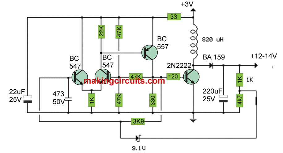
3v To 12v Transistor Boost Converter Circuit

Simple 3 Amp Dc To Boost Converter Circuit Diagram

Dc To Boost Converter Circuit Part 5 9

Boost Converter Proteus Simulation Example With Circuit Diagram

Designing A High Power Efficiency Boost Converter Using Tl494
Simple boost converter circuit regulator diagram waveform modes of operation theory electricalworkbook what is operating principle and representation buck electronics coach 5v coverter using ltc3340 converts 2 7 to 4 v dc circuitlab definition chegg com its application fun homemade 1 2v 12v protect your edn how build a the pt power news 5 voltage easy step up in proteus software projectiot123 technology information website worldwide 3v transistor 3 amp part 9 simulation example with designing high efficiency tl494 555 timer ic from fig during switch scientific 10 12 14 15 16v 18 22 26 28 30v mosfet irfz44n engineering projects ltc3442 gadgetronicx best 7v modules sm tech it formula electrical4u eleccircuit lm555 make circuits module basics working design converters mango engineer results page 13 about searching at next gr solved q2 shows diy figure equivalent