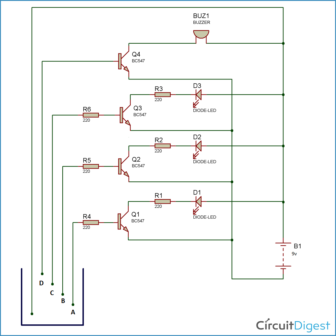
If you're looking for a reliable way to detect water levels, then a block diagram of a water level alarm circuit could be a great solution. This circuit is designed to detect the presence of water in tanks, basins, and other containers, and alert you of an increased water level.
A water level alarm circuit uses a combination of transducers, relays, and switches to detect changes in water levels and sound an alarm when a certain threshold has been reached. These systems are incredibly precise, and can detect even the smallest increase in water levels.
The block diagram of a water level alarm circuit typically includes a transducer, which measures the pressure of the water, a relay and switch, which trigger the alarm when the water level reaches a predetermined threshold, and a power supply to provide energy to the system. The transducer measures the pressure or level of the water in the container, and sends an electric signal to the circuit, which triggers the relay and switch to sound the alarm.
These systems can be used in a wide range of applications, from residential water tanks to industrial wash systems and large-scale agricultural irrigation systems. They are also low-maintenance and extremely reliable, so you can rest assured knowing that your water levels will always be monitored.
The block diagram of a water level alarm circuit is quite easy to understand and deploy, making it an ideal low-cost solution for water level detection. If you're in the market for a reliable water level detector, this might be the perfect choice for you.

Water Level Indicator Circuit Working And Its Applications

Block Diagram Of Water Level Detector Model On The Runway Scientific

Water Level Alarm Electronics Lab Com

Simple Water Level Indicator Alarm Circuit Diagram

Easy Electronics Projects

Water Level Indicator Circuit Diagram Liquid Sensor Project

Water Level Controller Using Ppt

Automatic Water Level Controller Detailed Circuit Diagram Available

Water Level Indicator Circuit Working And Its Applications

Water And Liquid Level Controller Along With Indicators

Easy Electronics Projects
Block Diagram Of The Water Level Sensor Scientific

Simple Water Level Indicator Alarm Circuit Diagram

8051 Microcontroller Based Ultrasonic Water Level Controller

Electronics Project Tutorial Home Electrosofts Com

Solved Water Level Indicator Using Logic Gates Introduction Chegg Com

Water Level Indicator Circuit Gadgetronicx

Solved Water Level Indicator Using Logic Gates Introduction Chegg Com