The blinking light schematic diagram is a crucial component of any electrical engineering project. It's a simple yet powerful tool that helps visualize how a circuit works and prevent wiring errors. However, many engineers get confused when creating one for their own project. Thankfully, it’s not as complicated as it seems. All you need is a few basic components and some creativity.
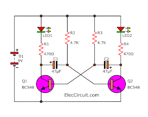
At first glance, you may think a blinking light schematic diagram is merely two LEDs connected in parallel. This could not be further from the truth. The real beauty of this design lies in the intricate web of resistors and capacitors that make up the complete circuit. Everything is strategically wired together so that the LEDs will flash in a desirable pattern.
To start building your own blinking light schematic diagram, begin by selecting two LEDs of different colors. Then, add two resistors to act as current limiting devices and two capacitors for time delay. Finally, you will need to choose an appropriate power source. The important thing to remember is that the current needs to be restricted in order for the LEDs to flash properly.
Once you have your components, the next step is connecting them together. Start by connecting one LED to the power source and then connect the other LED to the other resistor. The capacitors must then be linked in parallel with the LEDs and resistors. With everything connected correctly, you should be able to see your lights blinking.
Creating a blinking light schematic diagram might seem daunting at first, but it doesn't have to be. With a bit of patience and the right components, anyone can create a professional-looking circuit. So, get creative and start building your own. Your circuit will be one of a kind and you will be proud of the work you put into it.

220v Blinking Led Circuit

Results Page 79 About Flashing Led Searching Circuits At Next Gr

230v Ac Blinking Led Circuit

Blinking Led Circuit With Schematics And Explanation

Led Flasher Circuit With Relay

How To Build A Simple Blinking Led Circuit With Capacitor Transistor And Two Resistors Jon Gallant

5 Led Blinking Chaser Flasher Running Circuit Using Transistor

How To Make 12v Led Flasher With Sd Regulator Techsaw

Simple Dc Bulb Flasher Circuit

Blinking Led Circuit With Schematics And Explanation

3 Volt Led Flasher Light Circuit Using Transistors

Led Flashers Circuits And Projects Using Transistor Eleccircuit Com

Flip Flop Led Flasher Using Bc547 Transistors Lindevs

Flashing Light Circuit With Transistors

Bicolour Blinking Led Lights Circuit Bi Colour Flasher Dual

Flashing Led Battery Status Indicator Circuit Diagram And Instructions

Simple 2 Blinking Led Circuit Using Transistor Flasher

Led Flasher Circuit Diagram Using 555 Timer Blinking

Flashing Lights Circuit