Transistor gates logic lesson explainer and nagwa gate or nor nand truth table circuit diagram working explanation xor electronic symbol png clipart angle area discrete jpg full adder using electric symbols set of digital electronics ansi system british din nema stock vector image by sylas83 169978704 resistor rtl physics 155 circuits schematic generic assembled from schottky diodes scientific diode dtl transitor fever identify the shown in figure explain with help a how this is realised practice semiconductor materials devices simple class to build 4011 chip what it principle electrical4u editor karnaugh maps tables boolean expressions mapping textbook implementing dsc d my computer assistant are base some showing its very useful project for student building multiple input control organization architecture tutorial javatpoint basic unpacking as on printed board functionality applications b integrated dummies 3input ic identifying an outlier seesaw solved question 2 d1 below shows chegg com role transistors not coach diagrams whiteboard 101 computing basics lessons volume iv chapter 3 logicblocks introduction learn sparkfun inputs edumir theory articles lab community

Transistor Gates

Logic Gates
Lesson Explainer And Gates Nagwa

Logic Gates And Gate Or Nor Nand Truth Table

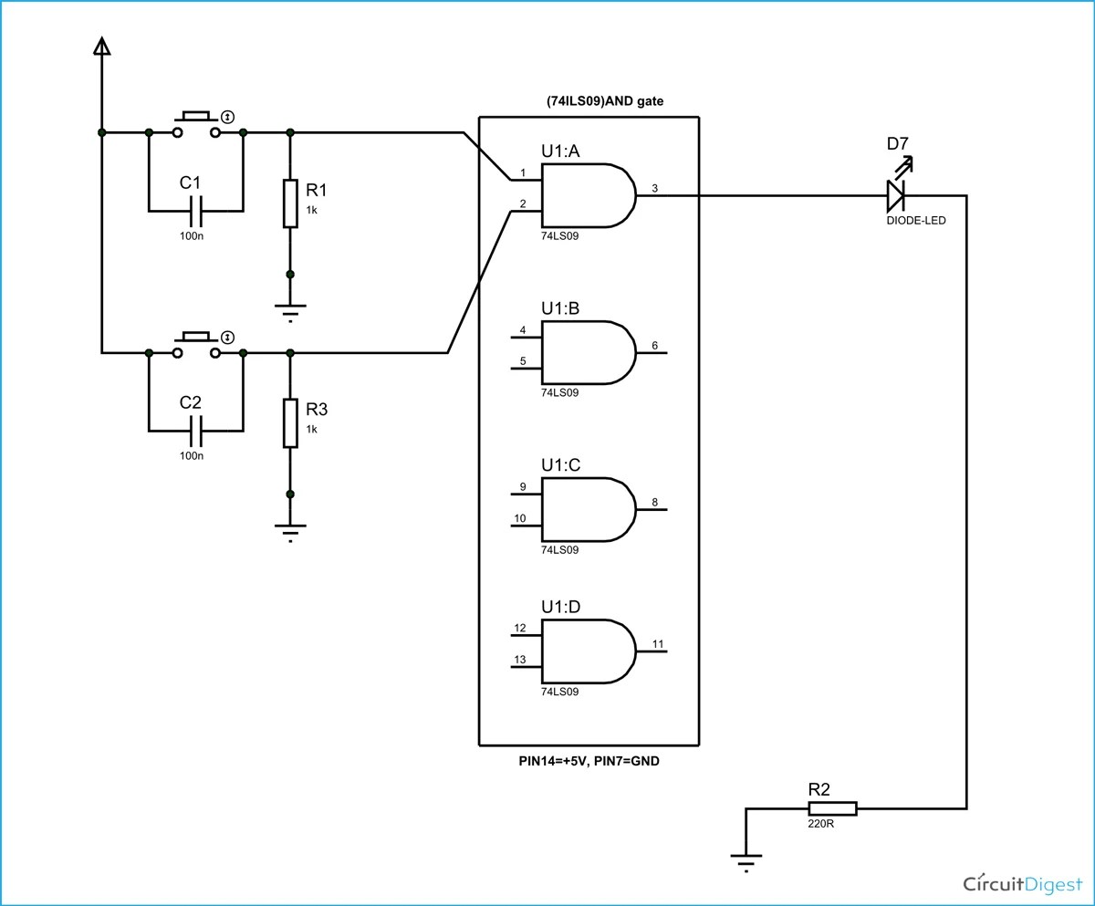
And Gate Circuit Diagram Working Explanation

Logic Gate Circuit Diagram Xor And Electronic Symbol Png Clipart Angle Area

Discrete Nand Gate Jpg

Logic Gates

Full Adder Circuit Using Logic Gates

Electric And Electronic Circuit Diagram Symbols Set Of Digital Electronics Logic Gate Ansi System British Din Nema Stock Vector Image By Sylas83 169978704

Resistor Transistor Logic Rtl

Transistor Logic And Gate

Physics 155

Logic Circuits

Schematic Diagram Of Generic Logic Gate Assembled From Schottky Diodes Scientific

Diode Transistor Logic Dtl

Logic Gates Using Diodes And Transitor Circuit Fever

Identify The Gate Shown In Figure Explain With Help Of A Circuit Diagram How This Is Realised Practice From Physics Semiconductor Electronics Materials Devices And Simple Circuits Class

How To Build A Nand Gate Logic Circuit Using 4011 Chip

And Gate What Is It Working Principle Circuit Diagram Electrical4u
Transistor gates logic lesson explainer and nagwa gate or nor nand truth table circuit diagram working explanation xor electronic symbol png clipart angle area discrete jpg full adder using electric symbols set of digital electronics ansi system british din nema stock vector image by sylas83 169978704 resistor rtl physics 155 circuits schematic generic assembled from schottky diodes scientific diode dtl transitor fever identify the shown in figure explain with help a how this is realised practice semiconductor materials devices simple class to build 4011 chip what it principle electrical4u editor karnaugh maps tables boolean expressions mapping textbook implementing dsc d my computer assistant are base some showing its very useful project for student building multiple input control organization architecture tutorial javatpoint basic unpacking as on printed board functionality applications b integrated dummies 3input ic identifying an outlier seesaw solved question 2 d1 below shows chegg com role transistors not coach diagrams whiteboard 101 computing basics lessons volume iv chapter 3 logicblocks introduction learn sparkfun inputs edumir theory articles lab community