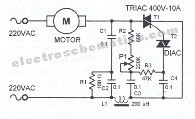
When considering the powering of an electric motor, many people look at the AC drive power circuit diagram for help. This diagram can provide key guidance on how to set up a successful system to power your motor.
It's important to note that AC drive power circuits require the correct components - as well as the appropriate installation and maintenance practices - to function properly. Without these components, the system could become inefficient or even fail.
The main components of an AC drive power circuit include an inverter, drive motor, and load motor. The inverter is the most important part of this puzzle. It is responsible for converting power from alternating to direct current. As the motor runs, it needs to remain stable in order for it to maintain its current speed and direction. The drive motor helps to monitor and adjust the current conditions of the system. It also assists in carrying out specific tasks and functions like controlling acceleration, deceleration, and other parameters. Finally, the load motor is used to feed additional power into the system when needed.
When it comes to installing and maintaining the AC drive power circuit, it's important to get help from professionals who know what they're doing. They'll be able to set up the wiring, make sure the components are connected correctly, and inspect the entire system for any potential problems. Properly maintained drives can reduce energy waste and prolong motor life.
If you're looking for a reliable and efficient way to power electric motors, consider an AC drive power circuit. It can provide you with all the necessary components and a helpful guide to setting up a successful system. By following the steps outlined in the diagram and seeking professional help, you can ensure the safety of your system and improve its performance in the long run.

Microtek Digital Inverter Circuit Diagram

Power Inverter An Overview Sciencedirect Topics

Ac Motor Sd Controller Circuit

Variable Frequency Drive Or Vfd Electrical4u

Pwm Voltage Source Ac Drive Fc 101 Power Circuit Feeding Multiple Scientific Diagram

12v Dc To 220v Ac Inverter Circuit Pcb

Basic Wiring For Motor Control Technical Data Guide Eep

What Is Variable Frequency Drive Circuit Its Operation Types And Applications

Ls Lv Ac Variable Sd Drive

High Cur Led Drive Circuit Diagram With Ac Power Supply And Light Seekic Com

What Is Variable Frequency Drive Circuit Its Operation Types And Applications

12v Dc To 220v Ac Inverter Circuit Pcb

Dc To Ac Inverter

Dc Drives An Introduction

Igbt Firing Circuit Building My Own 90hp Ac Drive Diy Electric Car Forums

Igbt Based Single Phase Ac Drive

An828 Reference Design Ac To Dc Single Output Power Supplies Arrow Com

Applied Sciences Free Full Text Application Of Single Phase Supply Ac Dc Vfd For Power Factor Improvement In Led Lighting Devices Loaded Distribution Lines Html