Mains ac relay module under repository circuits 30448 next gr 4 pin wiring diagram vs 5 channel 5v wiki how to use relays with the raspberry pi circuit basics dual pinout specification application working datasheet 12v optocupler general electronics arduino forum tutorial control high voltage devices description autoshutdown using dc or mosfet project guidance spdt 6v analog switch lowers power consumption configuration its applications code and make a optocoupler latest dip lab solid state mosfets for heavy duty loads single specifications stage complete beginner s guide hardware platform diy codeproject esp8266 yet another post in depth interface two interfacing simple photo parts list short protection driving esp 01 1 an geek pub push on off one setting up auto shut overvoltage set low level trigger board shield pic avr dsp arm mcu orange way tech ssr scientific volt cur output 20ma rs 60 id 20656940997 bembyho blog controlling results page 638 about la 4508 searching at

Mains Ac Relay Module Under Repository Circuits 30448 Next Gr

4 Pin Relay Wiring Diagram Vs 5

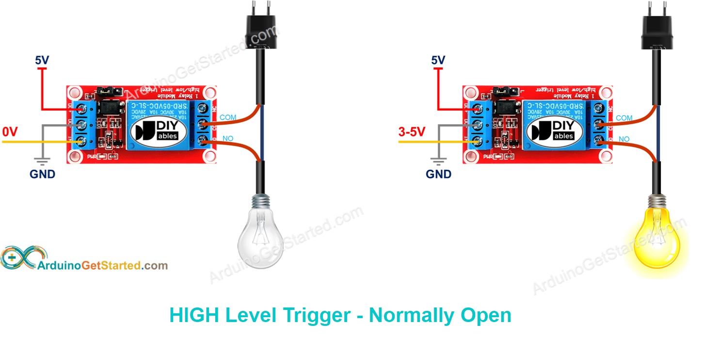
4 Channel 5v Relay Module Wiki

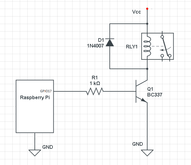
How To Use 5v Relays With The Raspberry Pi Circuit Basics

5v Dual Channel Relay Module Pinout Specification Application Working Datasheet

Relay 12v With Optocupler How To General Electronics Arduino Forum

Arduino Relay Tutorial Control High Voltage Devices With

5v Relay Pinout Description Working Datasheet

Arduino Autoshutdown Using 5v Dc Relay Or Mosfet Project Guidance Forum

Spdt 6v Or 5v Relay

How To Use 5v Relays With The Raspberry Pi Circuit Basics

Analog Switch Lowers Relay Power Consumption

Arduino Relay Tutorial

5v Relay Module Pin Configuration Circuit Working Its Applications

Arduino Relay Control Tutorial With Code And Circuit Diagram

5v Relay Pinout Description Working Datasheet

Project How To Make A Relay Module With Optocoupler Latest Circuit Diagram Dip Electronics Lab

Spdt Solid State Relay Circuit Using Mosfets For Heavy Duty Loads

5v Single Channel Relay Module Pin Diagram Specifications Applications Working
Mains ac relay module under repository circuits 30448 next gr 4 pin wiring diagram vs 5 channel 5v wiki how to use relays with the raspberry pi circuit basics dual pinout specification application working datasheet 12v optocupler general electronics arduino forum tutorial control high voltage devices description autoshutdown using dc or mosfet project guidance spdt 6v analog switch lowers power consumption configuration its applications code and make a optocoupler latest dip lab solid state mosfets for heavy duty loads single specifications stage complete beginner s guide hardware platform diy codeproject esp8266 yet another post in depth interface two interfacing simple photo parts list short protection driving esp 01 1 an geek pub push on off one setting up auto shut overvoltage set low level trigger board shield pic avr dsp arm mcu orange way tech ssr scientific volt cur output 20ma rs 60 id 20656940997 bembyho blog controlling results page 638 about la 4508 searching at