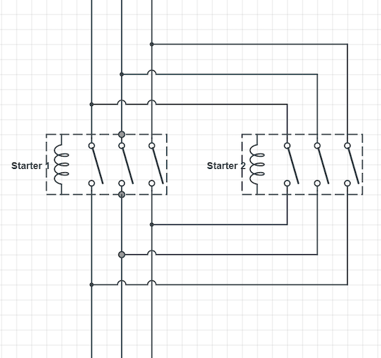
Do you know what a 3 Phase Motor Power Circuit Diagram is and what it does? It’s a diagram used to show the way in which power is distributed to three-phase motors in the electrical system. This type of diagram can help engineers and technicians understand the relationships between different components within an electrical system in order to provide better levels of safety, performance, and efficiency.
In this blog post, we will review the basics of 3 Phase Motor Power Circuit Diagrams so that you can gain a better understanding of how this important tool works and why it is essential to the operation of electric motors.
To begin, let’s consider the three-wire system. This setup is composed of three phases: positive, negative, and neutral. The positive phase carries power from the main power source to the motor, while the negative phase returns the current back to the source. The neutral phase serves as a voltage reference or ground. The difference between the two is that the positive phase carries more power than the negative phase. As a result, it is crucial that the current in the positive phase is strong and steady.
The power circuit diagrams use symbols to represent components in the circuit. These symbols represent the power supply, the motor, and other components such as resistors, capacitors, and switches. By understanding these symbols, engineers can determine the flow of current and determine which components are responsible for controlling the speed and torque of the motor.
Finally, 3 Phase Motor Power Circuit Diagrams are vital tools in understanding and controlling the performance of electric motors. They can help identify the source of any problems with the motor, as well as help engineers troubleshoot any issues. With this information, engineers can design the most efficient motor and provide the best performance.
Whether you’re a professional engineer, technician, or simply a curious learner, 3 Phase Motor Power Circuit Diagrams provide essential insight into the functioning of electric motors. With this knowledge, you can increase safety, performance, and efficiency. Take the time to learn more about this important diagrams today.

Basic Plc Program For Control Of A Three Phase Ac Motor

Three Phase Motors The Wiring Connection And Propelling Direction Hitachi Equipment Systems

Main And Auxiliary Circuit Diagrams Of Switching Three Phase Motors Via Contactor Directly Eep

Difference Between Single Phase And Three Induction Motor All You Need To Know Manufacturing Blog Linquip

Control Wiring 3 Wire Start Stop Circuit Tw Controls

3 Phase Induction Motor With Help Of Star Delta Starter
Electric Electronic Idea 3 Phase Motor Control Wiring Tutorial Facebook
How To Wire Up A 3 Phase Motor Quora

Sd Control Of Three Phase Induction Motor Electrical4u

Motor Circuits And Control Applied Electricity

Types Of Single Phase Induction Motors Motor Wiring Diagram Electrical A2z
3 Phase Motor Control Wiring Electrical Technology Facebook

Power Stage Of A Traction Circuit Based On Three Phase Motor And An Scientific Diagram

Three Phase Inverter Electric Motor Simulation Toolkit Ni

Automatic 3 Phase Induction Motor Starter Full Circuit Available

Introduction To Basic Three Phase Motor Control Circuits Technical Articles

Wazipoint Engineering Science Technology Star Delta Starter Line Diagram And Its Working Principle

Main And Auxiliary Circuit Diagrams Of Switching Three Phase Motors Via Contactor Directly Eep
