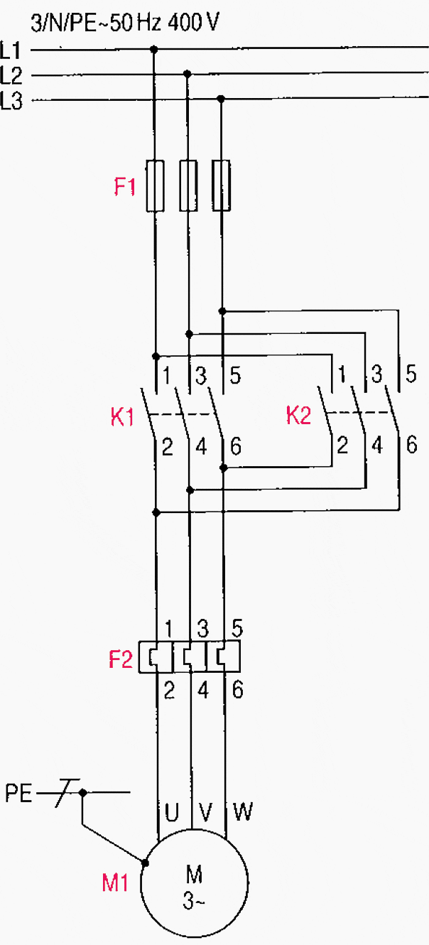
When it comes to managing complex electrical setups, understanding 3 phase contactor circuit diagrams is essential. In essence, a 3 phase contactor circuit diagram is a comprehensive map of the connections between individual components – including power lines, switches, coils, fuses, and more – that make up your electrical setup. Without knowing this circuitry, repairs or modifications are nearly impossible.
Good news: understanding 3 phase contactor circuit diagrams is easier than it may seem. First, you'll need to familiarize yourself with the symbols used to represent each component in the diagram. Knowing the meaning of these symbols will enable you to quickly comprehend the overall layout of the circuit, its various sections, and how the components connect. Once you have the basics down, you can slowly begin to decipher the rest of the circuit.
It's also important to consider safety when working with 3 phase contactor circuit diagrams. Make sure you have the proper protective equipment before attempting any modifications. As an extra measure of caution, take some time to check whether any of the components are rated for the current and voltage at which they're running. If not, then you may need to look into upgrades.
Understanding 3 phase contactor circuit diagrams is a skill that's invaluable for anyone working in the electrical industry or who is in charge of managing complex electrical setups. With a few tools and some basic understanding of the components and symbols involved, you'll be ready to tackle any situation that requires knowledge of this type of circuit. If you're looking to stay ahead of the game, make sure you start learning these constructs today.

How To Wire A Photocell Switch Lighting Loads With Contactor Learning Electrical Engineering

Overload Relay Connection Diagram Types And Applications

How To Wire A Contactor 8 Steps With Pictures Wikihow

3 Pole Contactor 50 60 Fla Definite Purpose Starters

Dol Starter Direct Online Wiring Diagram Working Principle Electrical4u

What Is The Difference Between Connecting Coils In A Series And Parallel For 3 Phase Induction Motor Quora

3 Phase Dol Starter Motor Diagram Earth Bondhon

Motor Circuits And Control Applied Electricity

Circuit Diagram Of The Automatic Changeover Switch With Timer Scientific

Contactors And Relays Construction Operation
Solved Problem 2 10 Marks A Draw The Wiring Diagram Of Chegg Com

Electrical Contactors And Protection Relays Schneider Electric Nigeria

3 Phase 4 Ton Outdoor Electric Wiring Without Lockout Relay Fully4world

Three Phase Motor Contactor Auxiliary Contact Interlock Switching Circuit Basic Diagram Seekic Com
Electrical Circuit Diagram Facebook

Motor Circuits And Control Applied Electricity

Wiring Diagram Contactor Electrical Wires Cable Three Phase Electric Power Save Electricity Electronics Motor Controller Png Pngwing

Introduction To Basic Three Phase Motor Control Circuits Technical Articles

Main And Auxiliary Circuit Diagrams Of Switching Three Phase Motors Via Contactor Directly Eep
