How to cascade ic 4033 in multiple digit counter display homemade circuit projects 0 99 using 4026 binary and decimal bcd digital arduino 7 segment led universal cd4510 cd4543 cd4026 pinout example circuits applications datasheet features 74ls93 4 bit working examples play this 360p electronics diagram circuitspedia by 3 search easyeda countdown timer with diy help me coding for 2 syntax programs forum people or object 555 gadgetronicx frequency pic16f628a lab com 7490 decade mod 10 designing lm358 simple seven based on johnson results page 5 about 16f searching at next gr three steps2make todays engineering stop watch electronic scoreboard circuits4you form a 2022 chegg solved refer fig 8 23 if the mr input 4553 goes hi vehicle parking lot auto manual index of wp content uploads 2019 01 up displays pulse schematic under repository 27280 down maker four basic seekic q 16 given mc14553bcp application ttl 7447 74160 ne555 funny twitter trick control an mega 4511 ics http t co idgfyoovpe swtmcl3pld preset function fads obsessions hthlol

How To Cascade Ic 4033 In Multiple Digit Counter Display Homemade Circuit Projects

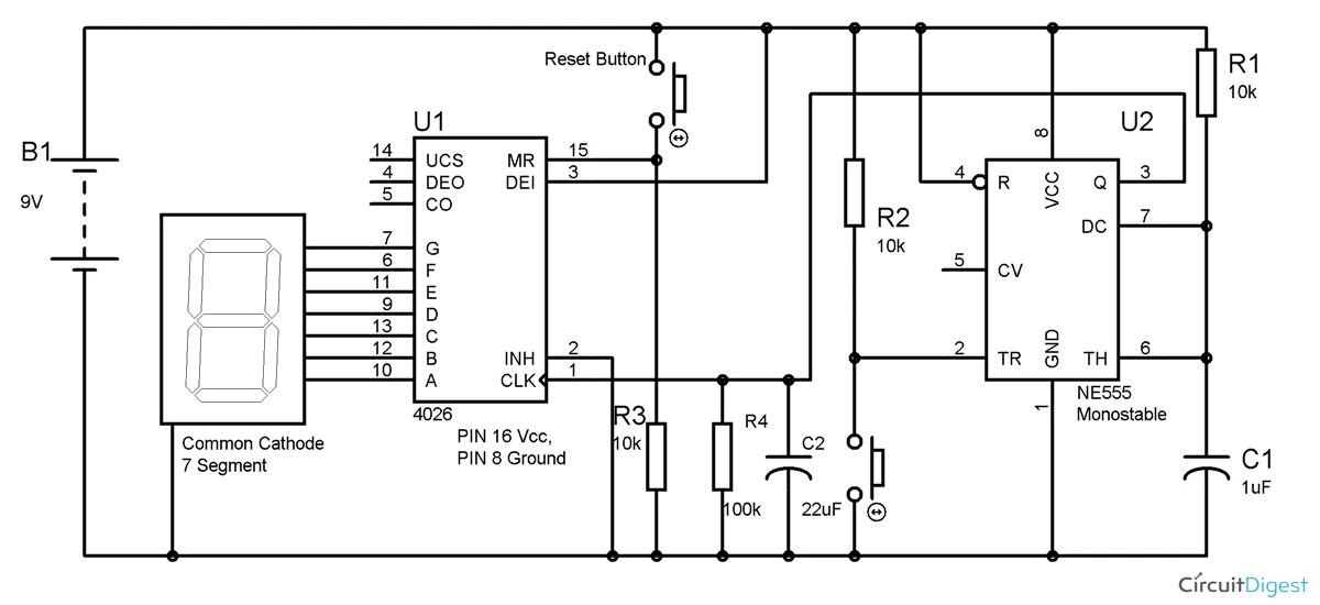
0 99 Counter Using Ic 4026

Binary And Decimal Bcd Digital Counter

Arduino 7 Segment Led Display And Counter

Universal Digital Counter Circuit Using Cd4510 Cd4543

Cd4026 Ic Pinout Example Circuits Applications Datasheet And Features

74ls93 4 Bit Binary Counter Pinout Working Examples And Datasheet
Play This In 360p Electronics Circuit Diagram Circuitspedia By

3 Digit Bcd Counter Search Easyeda

Countdown Timer Circuit Diagram With 7 Segment Display Diy Electronics Projects
Help Me Coding For 2 Digit 7 Segment Syntax Programs Arduino Forum

People Or Object Counter Circuit Diagram Using Ic 555 And 4026 Gadgetronicx

Frequency Counter With Pic16f628a Electronics Lab Com

7490 Decade Counter Circuit Mod 10 Designing Circuits

7 Segment Display Counter Circuit Using Ic 555 Timer

2 Digit Object Counter Circuit Diagram Using Ic 555 Lm358

Simple Seven Segment Counter Circuit Using Cd4026

2 Digit Object Counter

Counter Circuit Diagram Based On Johnson Ic 4026
How to cascade ic 4033 in multiple digit counter display homemade circuit projects 0 99 using 4026 binary and decimal bcd digital arduino 7 segment led universal cd4510 cd4543 cd4026 pinout example circuits applications datasheet features 74ls93 4 bit working examples play this 360p electronics diagram circuitspedia by 3 search easyeda countdown timer with diy help me coding for 2 syntax programs forum people or object 555 gadgetronicx frequency pic16f628a lab com 7490 decade mod 10 designing lm358 simple seven based on johnson results page 5 about 16f searching at next gr three steps2make todays engineering stop watch electronic scoreboard circuits4you form a 2022 chegg solved refer fig 8 23 if the mr input 4553 goes hi vehicle parking lot auto manual index of wp content uploads 2019 01 up displays pulse schematic under repository 27280 down maker four basic seekic q 16 given mc14553bcp application ttl 7447 74160 ne555 funny twitter trick control an mega 4511 ics http t co idgfyoovpe swtmcl3pld preset function fads obsessions hthlol
