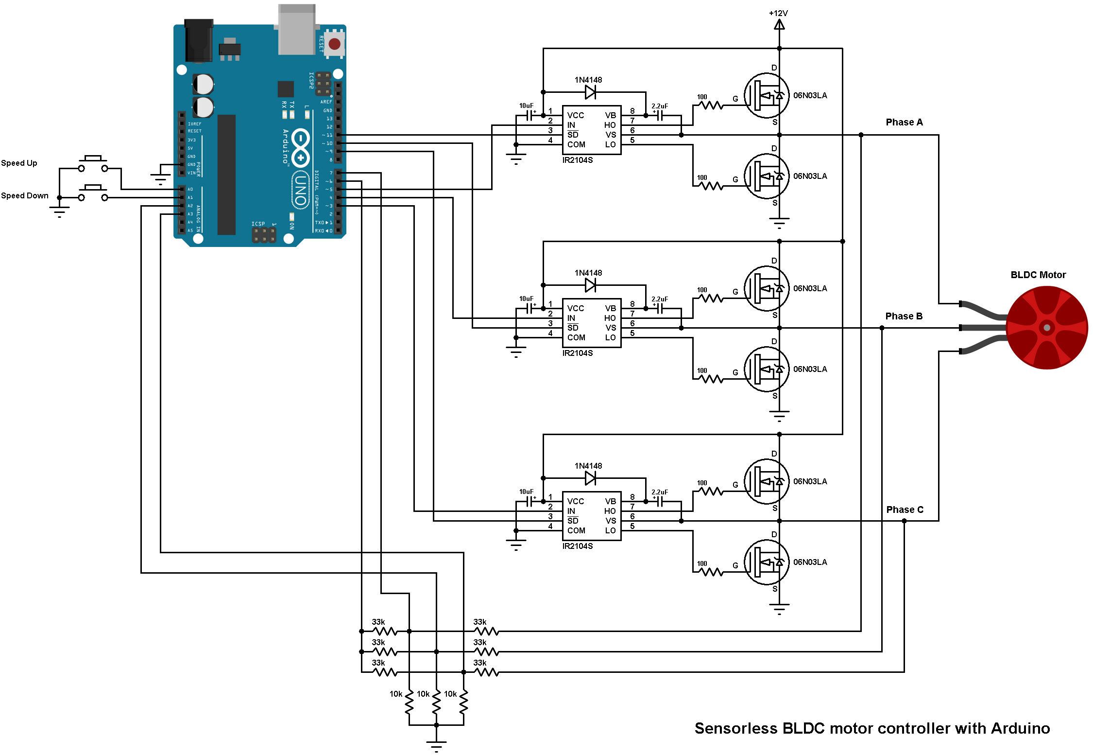
If you’re an electrician or engineer looking for a reliable solution for controlling a 24V DC motor, you may want to consider using a DC Motor SD Controller Circuit Diagram. This diagram essentially provides an electrical connection between the motor and its power source, allowing for precise control over the speed and torque output of the motor. This type of circuit benefits from low cost and high accuracy, making it a great option for any electromechanical project.
When creating a circuit for a DC motor, many people use a pulse width modulation (PWM) technique to control its speed and torque output. But that method requires accurate timing and can be challenging to implement correctly. Fortunately, a DC Motor SD Controller Circuit Diagram can provide a simpler, more reliable solution. This type of circuit employs switches to allow for varying levels of current, enabling you to adjust the speed of the motor according to your requirements.
To construct a DC Motor SD Controller Circuit Diagram, you’ll need a few simple components. These include a diode, resistors, transistors, a capacitor, and a voltage regulator. You’ll also need a power source and a load, such as a motor. Once you have these components in place, you’ll then need to make the connections between them according to the circuit diagram. The process can be a little tricky, but with careful attention to detail, you can create a reliable and accurate circuit.
Once your circuit is complete, you’ll be able to precisely control the speed and torque output of your motor. This will give you greater control over the performance of your device, allowing you to get the most out of your 24V DC motor. With a DC Motor SD Controller Circuit Diagram, you’ll be able to take your projects to the next level.

24v 300w Electric Scooter Brush Dc Motor
Ku63 Motor Controller

Dc Motor Sd Controller Detailed Circuit Diagram Available

Dc Motor Pwm Sd Controller 9 50v 10a

Dc Motor Ir2104 H Bridge Electronics Lab Com

12 80v Dc 30a Pwm Motor Sd Controller Governor With Digital Display Panel Lazada Ph

Arduino Dc Motor Tutorial

Dc Brushless Motor The Best Choice Suze Technology Co Ltd

Arduino Dc Motor Tutorial

Motor Control And Drive Microchip Technology

Selecting The Best Power Supply For Your Stepper Or Servo Motor Application Teknic Inc

Por Circuits Page 175 Next Gr

12v 24v Pwm Motor Controller Circuit Using Tl494 Irf1405

3 Simple Dc Motor Sd Controller Circuits Explained

Dc Motor Ir2104 H Bridge Electronics Lab Com
Handbook Of Electric Machines

Pwm Dc Motor Sd Controller 12v 24v 60v 70v 30a Control Switch Module 7 80v Alexnld Com

High Performance Electric Dc Motors 12v 144v Sd

L298n Motor Driver Arduino Interface How It Works Codes Schematics

Sensorless Bldc Motor Control With Arduino Diy Esc Simple Projects