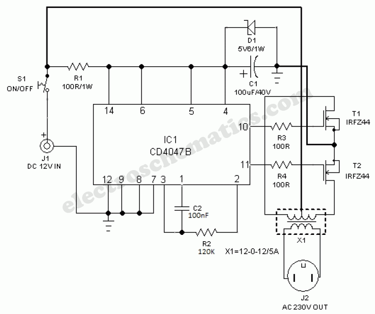
LEDs have grown increasingly popular for lighting purposes, but Compact Fluorescent Lamps (CFLs) still remain a prominent and viable option for many applications. A 12v 11w CFL circuit diagram can be useful for anyone looking to utilize this type of light in their projects.
CFLs offer several advantages over other light sources, such as lower power consumption and an extended lifespan. For a basic setup, they are relatively easy to install and use. The main components needed to build a 12v 11w CFL circuit include a diode, capacitor, a switch, and a transformer.
To put together a 12v 11w CFL circuit, the circuit must be wired correctly with the correct connection points. This typically starts with connecting the diode to the capacitor and then the collector of the transistor to the middle terminal of the capacitor. Once everything is connected, the transformer should be wired with two wires from the primary side going into the switch and two wires from the secondary side going into the socket.
After the wiring is complete, the switch should be toggled to the "on" position to power the CFL. This will initiate a flow of electricity through the circuit, creating light within the bulb. When the switch is flipped back to the "off" position, the power to the CFL will be cut off.
Incorporating a 12v 11w CFL into any project can be a great way to reduce energy costs and provide efficient and powerful illumination. While it may require some additional time and effort to understand and set up a circuit correctly, the end result can be incredibly beneficial to any lighting application. With the help of a 12v 11w CFL circuit diagram, setting up a reliable circuit can be easy.

Automatic Led Emergency Light Circuit

Typical Compact Flash Lamp Ballast Circuit 10 15 Fluorescent Scientific Diagram

Philips 11w 14w Ballast Choke For Cfl Light Veekaylight Com

Fluorescent Circuit Page 4 Light Laser Led Circuits Next Gr

12vdc Fluorescent Lamp Driver

A Simple Led Lamp Circuit From S Uses 5 And Takes Only 50 Ma
What Is The Use Of Transformer In Cfl Circuit Quora

Typical Compact Flash Lamp Ballast Circuit 10 15 Fluorescent Scientific Diagram

Automatic Led Emergency Light Circuit

Compact Fluorescent Lamp Under Repository Circuits 48386 Next Gr

Typical Compact Flash Lamp Ballast Circuit 10 15 Fluorescent Scientific Diagram

Solar Power Inverter Circuit

Compact Fluorescent Lamp Under Repository Circuits 48386 Next Gr

8w Fluorescent Lamp Driver

Cfl Lamps And Simple Inverter Delabs Electronic Circuits

Electronic Transformers Circuit Schematics 12v Halogen Lamp Electronics Projects Circuits

Cfl Emergency Kit Push Pull Application 12volt 18watt Circuits Diy

Electronic Transformers Circuit Schematics 12v Halogen Lamp Electronics Projects Circuits