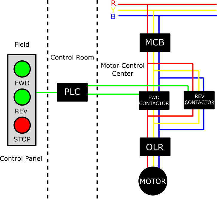
When it comes to understanding plc wiring diagrams, symbols are key. They make it easy to understand complex electrical systems and indicate the associated functions of each component. If you’re looking to further your knowledge of plc wiring diagrams and symbols, you’ve come to the right place.
Plc wiring diagrams are used in a wide variety of applications, including automation, robotics, and programmable logic controllers (PLCs). As such, it’s important for technicians and engineers to be familiar with these diagrams and the corresponding symbols. Each symbol represents a specific electrical component or function that is essential to the system.
The most common plc wiring diagram symbols include relays, which control electrical circuits, and switches, which break or open or close the circuits. Other common symbols include power sources, wires, transistors, vacuum tubes, connectors, and resistors. The symbols will also vary depending on the type of PLC being used.
It’s essential for technicians and engineers to know how to read these symbols, as making an error in interpreting them could cause serious problems. It’s important to always double-check the diagrams before beginning a project, to ensure that all the components are correct and in the correct sequence. Additionally, if you’re working with a complex system, consulting a technician or engineer could be beneficial.
In conclusion, symbols are an essential part of plc wiring diagrams. Knowing how to properly interpret these symbols can help prevent costly mistakes and potential problems. Be sure to double-check all diagrams and consult with a trained technician or engineer if necessary. Once you’re familiar with the various symbols and their meanings, you’ll be able to easily identify and interpret plc wiring diagrams.

Plc Symbols

Ladder Logic Symbols All Plc Diagram

Electrical Panel Wiring Diagram

Electrical Wiring Diagram Switches Symbols Automation Plc Programming Scada Pid Control System

Ladder Diagram Schematic Wiring Electrical Academia

Programmable Logic Controllers Plc Ladder Electronics Textbook

Pinball Trouble Shooting 1 By Russ Jensen

Ladder Logic Tutorial With Symbols Diagrams

Ladder Logic Tutorial With Symbols Diagrams

The Basics Of Reading Plc Panels And Wiring Diagrams Do Supply Tech Support

Wiring Diagrams Explained How To Read Upmation

Relay Circuits And Ladder Diagrams Control Systems Automation Textbook

Chapter5

What Is Ladder Diagram Edrawmax Online

Using Ladder Logic For Gray Code Conversion Plcdev

Ebook Automating Manufacturing Systems With Plcs
What Is An Electrical Symbol Quora