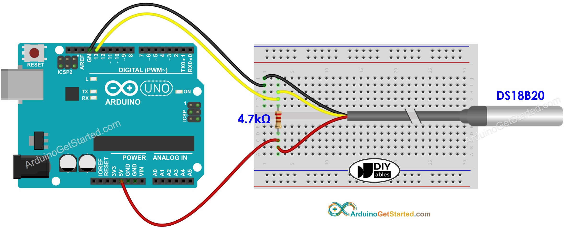
When it comes to controlling the temperature of your home, office, or industrial space, the wiring of your temperature sensor makes a huge difference. But understanding temperature sensor wiring diagrams can be confusing. In this blog, we’ll break it down step-by-step and explain the basics of temperature sensor wiring diagrams.
Temperature sensors regulate internal temperatures by sending signals to thermostats, fan controllers, and other temperature controllers. They are often used in commercial, industrial, or even residential settings to help maintain comfortable temperatures while reducing energy costs. The most common temperature sensors are thermistors, which measure and monitor temperature by changing their electrical resistance when exposed to temperature changes.
When wiring a temperature sensor, the first thing you need to do is connect the heat source to the temperature controller. This will allow the temperature controller to regulate the temperature. Next, the temperature sensing devices will need to be connected to the temperature controller. These sensing devices typically include thermistors, thermocouples, and RTDs (resistance temperature detectors).
Finally, the wiring diagram for your specific temperature sensor must be followed. Generally, the wiring diagram will tell you what type of wire is needed, the size of the wire, as well as which terminals need to be connected to the controller and the heat source.
Understanding the basics of temperature sensor wiring diagrams is essential for proper operation and safety. It’s important to make sure all wires are in the right position before connecting the device to the power source. Additionally, make sure the resistance is within the limits specified on the wiring diagram, as it can cause the temperature sensors to burn out if the resistance limit is exceeded.
By following the steps above, you can easily understand the basics of temperature sensor wiring diagrams and ensure that your temperature sensors are correctly wired to the temperature controller. Doing so will help keep your home, office, or industrial space comfortable and energy-efficient.

Arduino Temperature Sensor Oled Tutorial

Modifry S S2000 Ect Installation

Picprojects Net Ds1820 1 Wire Temperature Sensor

Arduino Temperature Sensor Tutorial

Toyota Corolla Repair Manual Circuit Description Engine Coolant Temperature Sfi System Diagnostics
Coolant Temperature Sensor Wiring Help Audi Forums

Help Wiring Up Temp Sensor And 2 Leads On Bmv 712 Victron Community

Modifry S S2000 Ect Display Driver

How To Wire Multiple Thermostats Together In Parallel

Coolant Sensor Wiring Pinout Yellow Vw Vortex Volkswagen Forum

Subaru Legacy Service Manual Dtc P0112 Intake Air Temperature Sensor 1 Circuit Low Bank Diagnostic Procedure With Trouble Code

Temperature Sensor Wiring Lead Color Code Engine

Diy Engine Coolant Temperature Sensor Replacement 2jzge I6 Sc300 Page 2 Clublexus Lexus Forum Discussion

Wiring The Ds18b20 1 Wire Temperature Sensor 14core Com

Pelican Ta1 Temperature And Alarm Sensor Wiring Diagram Manualzz

1 Wire Temperature Sensors Wiki Knowledge Base Teltonika Gps

Gm Coolant Sensor 12146312 Interface Sensors Arduino Forum
Wiring Diagram Of Temperature Sensor Figure 6 Exhibits The Connections Scientific

Toyota Ch R Service Manual Evaporator Temperature Sensor Circuit B1413 Air Conditioning System For Automatic With Top Mounted Conditioner Pressure