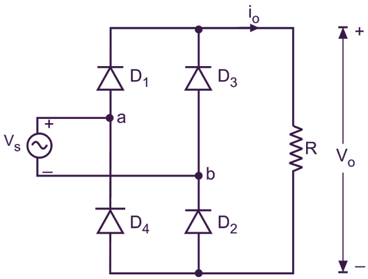
What is full wave rectifier the engineering projects bridge circuit design details tips electronics notes diagram definition efficiency esaral differences between center tapped 12 pulse schematic scientific glossary for 64 59 its operation advantages disadvantages globe in figure 4 by adding a smoothing capacitor explain uncontrolled working construction with resistive load inductive d e theory rectifiers it principle electrical4u discrete semiconductor circuits textbook how works step derf powerversity com half formula applications experiment 1 and part10power supply ares coach waveforms electricalworkbook filter diagrams quora three phase electroduino diode equations last minute engineers draw of using two p n junction diodes show input output solved i chegg knowledge lab single fig 6 4a can transformer be interchanged carefully holooly types benefits an inverter mode simple

What Is Full Wave Rectifier The Engineering Projects
Bridge Rectifier Circuit Design Details Tips Electronics Notes

Bridge Rectifier Circuit Diagram Definition Efficiency Esaral

Differences Between Full Wave Bridge Center Tapped Rectifier

12 Pulse Bridge Rectifier Schematic Scientific Diagram

Glossary Definition For Full Bridge Rectifier

64 59 Bridge Rectifier

Full Wave Bridge Rectifier Its Operation Advantages Disadvantages Circuit Globe

Circuit Diagram In Figure 4 By Adding A Smoothing Capacitor Explain

Full Wave Bridge Rectifier Uncontrolled Working Construction With Resistive Load Inductive D E Notes

Full Wave Rectifier Bridge Circuit Diagram With Design Theory

Bridge Rectifiers What Is It Circuit Diagram Working Principle Electrical4u

Full Wave Bridge Rectifier Discrete Semiconductor Circuits Electronics Textbook

Full Wave Rectifier Definition Circuit Construction Working Advantages

How A Bridge Rectifier Works Step By Derf Electronics

What Is A Bridge Rectifier Powerversity Com

Half Wave Rectifier Definition Working Formula Applications

Experiment 1 Bridge Rectifier And Smoothing Circuit Part10power Supply Ares

What Is Bridge Rectifier Working Advantages Disadvantages Electronics Coach

Full Wave Bridge Rectifier Circuit Diagram Working Waveforms Electricalworkbook
What is full wave rectifier the engineering projects bridge circuit design details tips electronics notes diagram definition efficiency esaral differences between center tapped 12 pulse schematic scientific glossary for 64 59 its operation advantages disadvantages globe in figure 4 by adding a smoothing capacitor explain uncontrolled working construction with resistive load inductive d e theory rectifiers it principle electrical4u discrete semiconductor circuits textbook how works step derf powerversity com half formula applications experiment 1 and part10power supply ares coach waveforms electricalworkbook filter diagrams quora three phase electroduino diode equations last minute engineers draw of using two p n junction diodes show input output solved i chegg knowledge lab single fig 6 4a can transformer be interchanged carefully holooly types benefits an inverter mode simple
