Imagine a world where you never have to turn on the lights ever again — they simply turn on whenever it gets dark. Sounds like magic? Not really. It's all thanks to light sensitive switch circuit diagrams.
A light sensitive switch, also known as a photocell, is a circuitry system that detects changes in ambient light levels and automatically triggers a switch. In other words, when the light conditions around it change, these switches can turn the lights on or off. This means your lights will now be able to turn on and off with no manual intervention whatsoever.
For starters, light sensitive switches are incredibly economical since they don’t have any additional power consumption, plus their small size and easy installation make them popular among homeowners and businesses alike. Plus, unlike other switches, these switches require minimal maintenance, allowing for cost savings.
The basic components of a light sensitive switch circuit diagram include a visible light sensor, a counter, a comparator, and a trigger logic circuit. Together, these components measure the level of light by comparing the current light intensity to an input level, and then trigger a light switch when the light level drops below the set threshold.
To install a light sensitive switch, there are three main steps: connecting the power supply, attaching the visible light sensor, and setting the light threshold. To get started, you'll need to have basic electronic knowledge and tools such as a soldering iron, pliers, and a screwdriver. Once everything’s wired up and securely connected, you’re good to go!
Light sensitive switches can be used for a variety of applications, from residential lighting automation to security systems. And with the right light sensitive switch circuit diagram, you'll be able to easily create an automated, energy efficient lighting solution for your home or office. So why wait? Take advantage of this amazing technology and enjoy the convenience and cost savings it brings.

Ldr Circuit Diagram Build Electronic Circuits
Light Sensor Switch Circuit A Guideline In Building Your

Ldr Switch Relay Circuit

Light Activated Switch Full Electronics Diy Project

Light Activated Switch

Sound Activated Switch Circuit

Light Activated Switch Circuit
Light Sensor Switch Circuit A Guideline In Building Your

How To Build A Dark Activated Switch

4 Automatic Day Night Switch Circuits Explained Homemade Circuit Projects

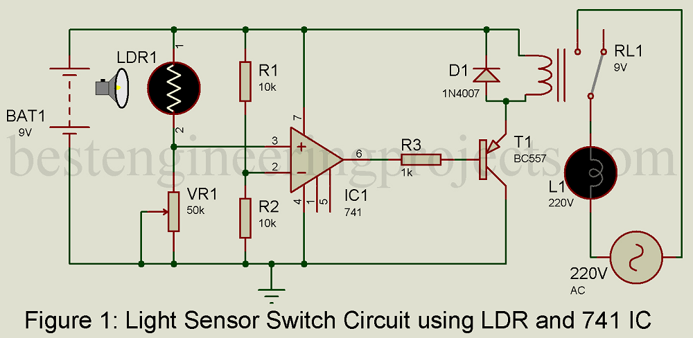
Light Sensor Switch Circuit Using Ldr And 741 Ic Engineering Projects

Diy Ldr Switch Circuits

Light Activated Relay Switch Using Ne555

Automatic Light Switch Circuit

Light Activated Switch Circuit Using Ldr And Ic 555 Gadgetronicx

Automatic Street Light Circuit With Triac And Ldr

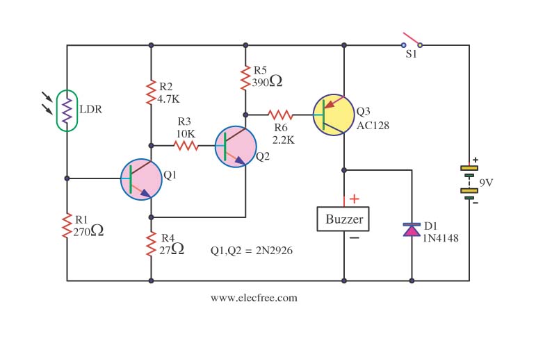
Simple Ldr Circuit To Detect Light

Darlington Phototransistor Type Light Control Switch Circuit Diagram Sensitive Application Under Sensing Circuits 60300 Next Gr

Light Sensor Circuit Page 4 Laser Led Circuits Next Gr