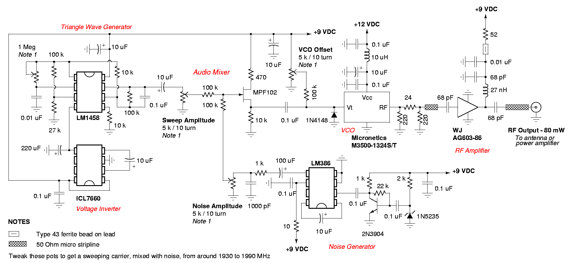
Have you ever been in a situation where you needed some peace and quiet, but your phone's constant buzzing and ringing wouldn't let you have it? Maybe you were trying to focus on an important task at work, catch up with a friend over coffee, or simply relax and enjoy some alone time. Whatever the case may be, we've all been there. And that's where a circuit diagram of a mobile signal jammer comes into play.
For those unfamiliar with the concept, a mobile signal jammer is a device that blocks cell phone signals, preventing them from receiving and transmitting any data. This means that any phones within its range will not be able to make or receive calls, send or receive texts, or access the internet.
So how does it work? The circuit diagram of a mobile signal jammer consists of various electronic components such as transistors, capacitors, resistors, and antennas. These components work together to create a radio frequency (RF) blocker, which interferes with the signals between the cell phone and the nearest cell tower.
When a cell phone is switched on, it constantly sends out signals to connect with the nearest cell tower. The mobile signal jammer disrupts these signals by emitting a stronger RF signal, effectively blocking the communication between the phone and the tower. This results in a "dead zone" where no calls or messages can go through.
While the use of mobile signal jammers is controversial and banned in many countries due to concerns about public safety and emergency communication, they have proven to be useful in certain situations. For example, in places like schools, libraries, and movie theaters, where disruptive phone use can be a major nuisance, using a mobile signal jammer can help maintain a peaceful and distraction-free environment.
However, it's important to note that while using a mobile signal jammer may seem like a quick and easy solution, it also has its limitations. It can only block signals within a specific range and cannot target specific phones. Plus, it's important to use it responsibly and avoid interfering with critical communication channels.
In conclusion, the circuit diagram of a mobile signal jammer may seem complex, but its purpose is simple – to provide some peace and quiet in a world where constant connectivity can sometimes become overwhelming. So next time you find yourself in need of a break from technology, just remember that there's an electronic solution for that.

Spy Phone Bug Transmitter Circuit

Circuit Diagram Of Mobile Jammer 2022 2023 Studychacha

Tv Remote Signal Jammer Circuit

Results Page 287 About Number Guessing Circuit Searching Circuits At Next Gr
![]()
Anti Tracker Mini Gps Signal Jammer Blocker Dc12v For Car China Made In Com
Signal Jammer And Its Applications
Copy Of Mobile Signal Jammer Multisim Live

How To Make A Cellphone Jammer Circuit Explored
ទស សន វដ ដ អ ឡ ចត រ ន ចកម ព ជ

How Do Cell Phone Jammers Work Quora
Signal Jammer And Its Applications

Review Teardown Of A Cheap Gps Jammer

Phone Fm Transmitter Circuit Diagram

Emp Jammer Search Easyeda

Rf Archives Gadgetronicx

Cell Phone Jammer Circuit

Cell Phone Detector

How To Make Mobile Signal Jammer Circuit Digest

Nb638 Wide Vin 4 5 28v 7a Cot Synchronous Step Down Converter With Internal Bias Supply Ultra Sonic Mode At Light Load Mps