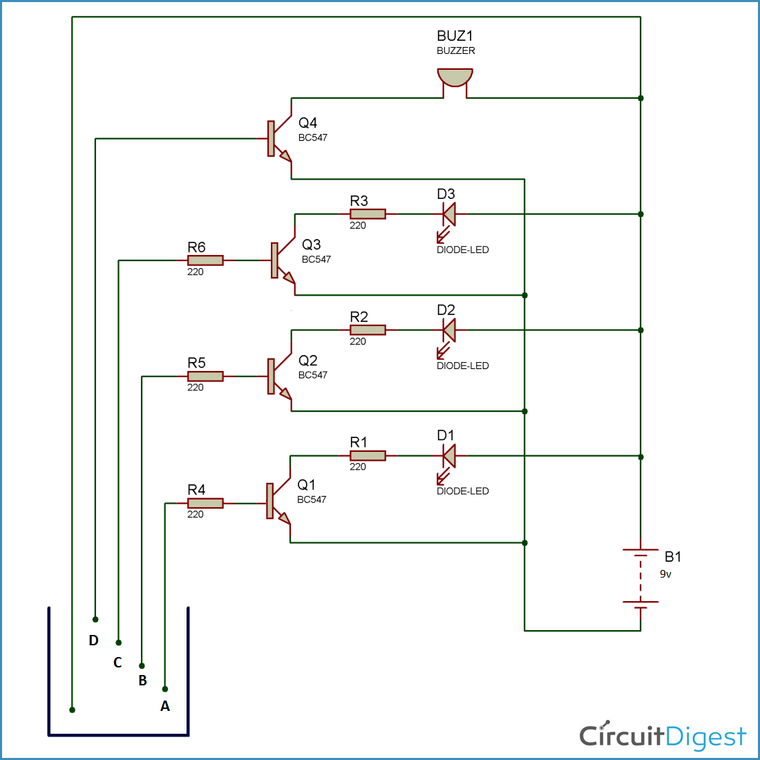
Load cell indicator circuit diagram is an essential tool for any electrical engineer. From monitoring signal strength and voltage to controlling the speed and strength of a motor, load cell indicators are used in almost all applications involving electricity. But how can you make sure that your load cell indicator circuit diagram is accurate and safe?
In its simplest form, a load cell indicator circuit diagram is a diagram that helps electrical engineers identify the right components and layout for a given project. This type of diagram usually consists of components like resistors, transistors, transducers, and other items which must be connected in a certain way in order to work correctly. By using this circuit diagram, it is possible to identify any potential issues with the circuit, as well as understand how different components will interact with each other.
However, the most important thing to note about a load cell indicator circuit diagram is that it should be tailored to the individual application. For example a system for controlling motor speed may require different components than one for monitoring the voltage of a power supply. It is therefore important to ensure that the circuit diagram used for a given project reflects the actual requirements and layout of the components.
In addition to being tailored to the project, it's important that the load cell indicator circuit diagrams are properly constructed. This means that the lines and components should be clearly marked, as well as being positioned in the correct position in order to facilitate easy understanding of the circuit. Additionally, the dimensions of the components should match the specifications of the actual hardware they will be connected to.
Finally, it is important that the circuit diagram has been tested before use. While this might seem like an obvious step, it is incredibly important to ensure that the circuit will actually work correctly. Any errors or inconsistencies in the circuit could result in dangerous outcomes, so it is worth taking the extra time to double check the accuracy of the diagram.
By following these key steps, any electrical engineer can ensure that their load cell indicator circuit diagram is up to date and effective. As long as the circuit has been researched, designed, and tested properly, then it can be safely used in any application. It is therefore essential that the circuit is regularly reviewed and updated in order to ensure maximum safety and reliability.

N Fuse Indicator

Circuit Design For Mobile Incoming Call Indicator Eeestudy

Call Indicator

8 Low Battery Voltage Alarm Indicator Circuits Using Scr Transistor Ic

How To Choose A Loadcell Unipulse

Results Page 266 About Ultrasonic Pest Repeller Circuit Diagram Searching Circuits At Next Gr

Short Circuit Indicator

Simple Water Level Indicator Alarm Circuit Diagram

8 Low Battery Voltage Alarm Indicator Circuits Using Scr Transistor Ic
Schematic Of Water Level Indicator Scientific Diagram

Electrical Engineering Tutorials Lm1830 Based Liquid Level Indicator Circuit

Getting Started With Load Cells Learn Sparkfun Com

Water Level Indicator Circuit Using Cmos Ics Under Repository Circuits 25344 Next Gr
Water Level Indicator All About Circuits

Simple Water Level Indicator Circuit Using Logic Ic Circuits Diy
Mobile Incoming Call Indicator Circuit Diagram And Working
Water Level Indicator Under Repository Circuits 35884 Next Gr

N Fuse Indicator Circuit

Load Cell Electrical Circuit Utilcell