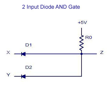
It’s a circuit diagram—the kind of image you may come across in the engineering field. It's for an AND gate using two diodes.
For those not familiar with the specialist knowledge, a gate is a binary logic device with two inputs and one output. It is designed to work on a high/low, 1/0 voltage level. An AND gate will only give an output if both its inputs are in the ON state.
The two diodes in the circuit diagram are placed between the two input signals of the AND gate. When both inputs are in the ON condition, current flows through the two diodes and out of the output of the AND gate. Because diodes block current when not triggered, this means that when one or both of the inputs are not in the ON state, no current will flow and the output of the AND gate will be off.
Using diodes to build logic gates is a common practice in electrical engineering, as it makes common logic operations—like AND, OR, NOT, NOR, NAND—much simpler and more efficient. Furthermore, the wiring of these logic gates is generally easier than with transistors and, although the output current capability is less, the power wasted in their operation is generally much lower.
The AND gate circuit diagram in this example is a powerful and reliable tool for electrical engineers. It is a great illustration of the principles of digital logic: how a combination of low- and high-voltage states can be used to create dynamic systems. This demonstration of simple electrical engineering shows how basic circuits like this one can be combined to produce a complex system. It also highlights the importance of reliable components and thorough testing in the design process.
Overall, the AND Gate circuit diagram is an effective tool for anyone working in the electrical engineering field, offering a neat summary of one of the most important concepts in digital logic. With its simple design, it’s easy to understand, use, and maintain.

Designing An And Gate Using Transistors

Xnor Gate Using Rtbt Scientific Diagram

Diode And Transistor Nand Gate Or Dtl Ics Electrical4u

Dtl Or Gate

Schematic Diagram Of Generic Logic Gate Assembled From Schottky Diodes Scientific

Diode Logic Circuits And Gate Or

3 2 The Not Gate

And Gate Using Diodes On Breadboard In Detail
Draw Circuit Diagram For Two Input Diode Or Gate And Also Explain Their Working Give Truth Table Sarthaks Econnect Largest Online Education Community
Solved Experiment No 2 Diode As A Switch Objective S The Chegg Com

Experiment 1 Diode Logic Circuit Part13fundamental Ares

Nand Gate Using Diode Circuit

Diode Transistor Logic Dtl

Unit 8 Logic Gates Ppt Online

Solved Figure Q4 Shows An Implementation Of A Logic Gate Chegg Com

Perform The Xor Xnor Function With A Diode Bridge And Transistor Edn

Digital Electronics Logic Gates Basics Tutorial Circuit Symbols Truth Tables

How To Build A Diode And Gate Circuit
Why Can T We Use Diodes To Make A Not Gate Quora