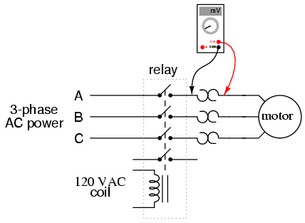
Have you ever wondered how 3 phase motors get their power? The process for powering a 3 phase motor requires a special wiring diagram, which will ensure that the correct amount of electricity is fed to the motor. This guide will walk you through the details of 3 phase motor circuit wiring diagrams.
Three-phase electric power is usually supplied to large industrial motors in commercial and industrial applications. In these installations, three individual phases of alternating current (AC) are transmitted along three phase wires. This type of wiring allows multiple devices to be connected together without an additional neutral connection, and it also allows motors to maintain consistent speed regardless of the load placed on them.
When wiring 3 phase motors, one of the most important considerations is the proper selection of the wiring diagram. This diagram must show the correct connections between the motor, power source, and other components. It should also include information about the type of current used in the circuit, the size of the wires, and other safety features such as surge protection and harmonic analysis.
It's important to remember that not all 3 phase motors are the same. Different types of motors require different wiring diagrams. When selecting a wiring diagram, make sure to choose one that is specifically designed for the type of motor you are working with.
When wiring 3 phase motors, it's also important to make sure all of the components are properly wired. Improperly wired components can cause problems such as overheating, short circuits, and power outages. Taking the time to double-check your work is highly recommended, both during and after the installation.
Finally, it's important to remember that 3 phase motor circuit wiring diagrams are not plug and play. Each wiring diagram must be tailored to the specifics of the motor and power source being used. Doing so provides the best outcome and ensures safe and reliable operation.
Single Phase Motor Connection Diagram And Wiring Procedure Etechnog

Starting Three Phase Squirrel Cage Induction Motors
Three Phase Motor Wiring Diagram Electrical Technology Facebook

Introduction To Basic Three Phase Motor Control Circuits Technical Articles

Y Δ Transform Electric Motor Wiring Diagram Three Phase Power Starter Others Electronics Electrical Wires Cable Engine Png Pngwing

Motor Circuits And Control Applied Electricity

Main And Auxiliary Circuit Diagrams Of Switching Three Phase Motors Via Contactor Directly Eep

How To Wire Motor Sd Or Direction Controller Huimultd
3 Phase Motor Control Wiring Electrical Technology Facebook

Three Phase Motors The Wiring Connection And Propelling Direction Hitachi Equipment Systems
Three Phase Motor Connection Diagram And Wiring Procedure Etechnog
Wiring Of Three Phase Motor Scientific Diagram

Introduction To Basic Three Phase Motor Control Circuits Technical Articles

Magnetic Starter Wiring An Allen Bradley 709 3 Phase For Single 220v The Hobby Machinist

Sequential Motor Control Circuit 3 Diagrams With Switch Timer Plc
Electrical Electronic Systems Forward Reverse 3 Phase Ac Motor Control Wiring Diagram Star Delta Main Circuit 1 Mcb Mini Circut Breaker 2 Fc

Main And Auxiliary Circuit Diagrams Of Switching Pole Changing Three Phase Motors Eep

Electrical Protection Of 3 Phase Motors Types And Schemes Learning Engineering

Msi 22 Panel Kw 3 Phase 400 V Nist Control Systems Pty Ltd


