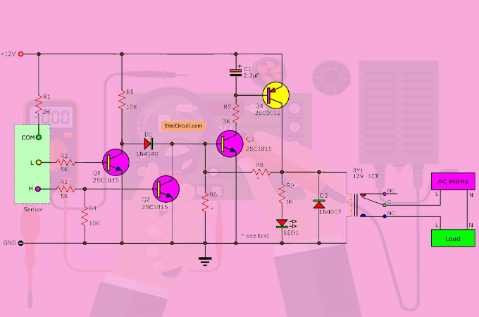
Circuit diagrams are one of the most important tools for electrical engineers. They are a great way to visualize how different components of an electronic circuit work together, and they can help you troubleshoot problems in the system.
But what is a circuit diagram exactly? A circuit diagram is a graphical representation of an electric circuit. It uses symbols to represent the components that make up the circuit, such as resistors, capacitors, diodes, transistors, and other elements. It also shows the paths of the electrons in the circuit along with the voltage and current in each part of the circuit. This allows engineers to quickly understand how the components of the circuit are interacting and how they should be connected to get the desired output.
Circuit diagrams are used in almost every modern electrical engineering project. From transistor radios to smartphones, circuit diagrams are essential for designing electronics that are safe and reliable. Engineers use circuit diagrams to plan out how the components should be laid out on a PCB, and to ensure that the components are connected correctly. They also use them to diagnose faults within the system, saving time and money.
Circuit diagrams can be complex and hard to understand, but with practice and experience, it becomes easier to interpret them. It is important to understand the basics of how a circuit works before attempting to read a circuit diagram. Once a basic understanding is established, engineers can begin to analyze the circuit and make optimal adjustments to its design.
Whether you are a novice engineer or an experienced professional, circuit diagrams are an essential tool for designing and troubleshooting electrical systems. By building a familiarity with circuit diagrams, engineers can better understand how each component of a circuit interacts with others in order to create the intended result.

Sample Circuit Diagrams From Both The No Labels N Conditions Only Scientific Diagram

And Circuit Figure 8 Or Scientific Diagram

Circuit Diagram Software

Resources

Main And Auxiliary Circuit Diagrams Of Switching Three Phase Motors Via Contactor Directly Eep

Or Gate Circuit Diagram Using Ic 74ls32

Circuit Diagrams Tutorial Electronics Diagram General Theory Tutorials Circuits Hobby Projects

Electrical Components And Systems Topic 3 Practising With

10 Best Free Online Circuit Diagram Makers In 2022

Difference Between Pictorial And Schematic Diagrams Lucidchart Blog

Schematics And Wiring Diagrams Circuit 1

Electronic Diagrams Prints And Schematics Instrumentation Tools

Physics Tutorial Circuit Symbols And Diagrams

Difference Between Pictorial And Schematic Diagrams Lucidchart Blog

How To Read A Schematic Learn Sparkfun Com
What Is Relay Switch Circuit Diagram And Working Principle Etechnog

Electric Circuit Diagram Images Browse 17 952 Stock Photos Vectors And Adobe

Electronic Schematics What You Need To Know
