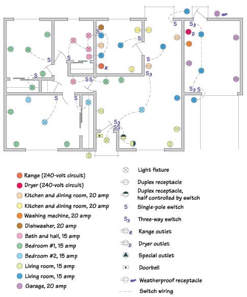
Sure, wiring diagrams may look a bit intimidating, but knowing what the different symbols mean and how to use them can make branch circuit wiring a lot less daunting. In this blog post, we will explain what a branch circuit wiring diagram is and how it should be interpreted when working with electrical systems.
A branch circuit wiring diagram is a detailed visual representation of an electrical circuit, allowing an electrician to easily identify components and how they are connected. The diagram is usually drawn from the perspective of the device being worked on so that any connection points, switches, and outlets can be easily identified and wired properly. It also shows the path of current in the circuit, which is critical for making sure all components are connected correctly.
When reading a branch circuit wiring diagram, the most important thing to remember is that each icon represents a specific device or feature. For example, a red/white line indicates a 240V switched outlet in the United States. Knowing this is essential when connecting devices correctly. Additionally, when reading the diagram, you may need to identify any terminals or connection points that may have been used to connect the various devices in the system.
Finally, it's important to keep in mind the physical layout of the wiring when interpreting a branch circuit wiring diagram. The diagram may be drawn in such a way as to give a general layout of the individual components, but if the physical layout of the wiring does not match the diagram, then the diagram may not be correct. This is why it's important to double-check the actual wiring before making any connections.
In conclusion, understanding how to read and interpret a branch circuit wiring diagram is essential for any electrician. By understanding the icons, connections points, and physical layout of the wiring, electricians can easily and safely work with electrical systems.

How To Wire A 3 Way Switch Wiring Diagram Dengarden

How A Home Electrical System Works

Radial Circuit With Branches

National Electrical Code Multiwire Branch Circuit Transworld Electric

Setting Up Your Progressive Dynamics Ac Dc Panel Lightharvest Solar
Circuit Breaker Wiring Diagrams Do It Yourself Help Com

Branch Circuit Testing Ppt

Electric Circuits It S All About Nodes Branches And Loops

Electrical System In Buildings Archtoolbox

Branch Circuits Part One Ec M

System And Process For Automated Circuiting Branch Circuit Wiring Diagram Schematic Image 38

How To Map House Electrical Circuits

Ch 3 Determining The Required Of Branch Circuits Lighting Outlets Receptacle Flashcards Quizlet

Multiwire Branch Circuits Nec 210 4 Jade Learning

Electrical Drawing For Architectural Plans

Appendix B Site Power And Cables

Branch Circuit Feeder And Service Calculations Part Xlv Electrical Contractor Magazine

210 19 A 1 Branch Circuits

Circuit Drawings And Wiring Diagrams Description Lesson
