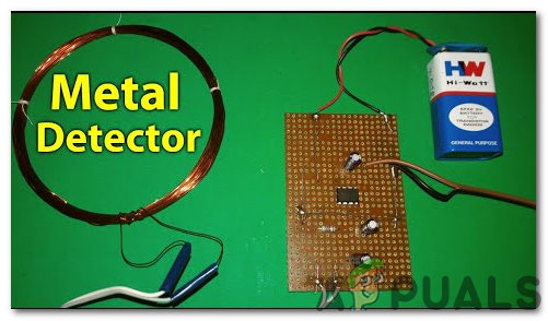
The metal detector schematic circuit diagram has long been a mystery to many treasure hunters and metal detector hobbyists. But, with the advent of modern technology, metal detector circuits have become easier to understand and build.
For those looking to build their own metal detector, understanding the metal detector schematic circuit diagram is the first step in the process. This diagram provides a wealth of information on how your metal detector will work and what components you need to build it.
The metal detector schematic circuit diagram outlines all of the different components necessary for a successful metal detector. For example, it includes the AC power supply, the detector head, a processor board, and a transmission coil. Without these components, your metal detector cannot detect metal objects.
The circuit diagram also provides information on how the various components should be connected to each other. This will ensure that your metal detector is properly wired and that it can detect small and large metallic objects accurately and consistently.
In addition to helping you understand the components needed to build your metal detector, the metal detector schematic circuit diagram can also serve as a blueprint for those looking to build their own metal detector from scratch. It is important to note that some components are essential for the metal detector to function properly, while others are “optional” and can be left out if not needed.
Finally, understanding the metal detector schematic circuit diagram can help you troubleshoot problems or make modifications to your metal detector that may be required depending on different environments or varying metal objects.
The metal detector schematic circuit diagram is an invaluable tool for hobbyists and treasure hunters alike. With its detailed outline of the components needed and their proper wiring, it is a great reference for those looking to build their own metal detector.

Sensors Detectors Metal Electronic Circuits

Results Page 5 About Metal Searching Circuits At Next Gr

Metal Detector Circuit

Ferrous Non Metal Detector Circuit

Pulse Induction Metal Detection Schematic Circuit Scientific Diagram

Surfmaster Pi Metal Detector Schematic Diagram

Simple Sensitive Metal Detector Circuit Electronics Projects Circuits

Metal Detector Using 555 Timer Circuit

How To Make A Metal Detector Circuit Appuals Com

Find Concealed Metal Pipes Nails Studs Using This Circuit

Pulse Induction Metal Detection Schematic Circuit Scientific Diagram

Metal Detector Using Arduino

Build Your Own Metal Detector With An Arduino Projects

White S Schematics Hack Review

Circuit Diagram Of Metal Detector Umiv 1

Metal Detector Circuit Using Beat Frequency Oscillator Bfo Homemade Projects

Basic Circuitry Of Metal Detection

Simple Metal Detector Module

Heathkit Groundtrack Gr 1290 Metal Detector Schematic Diagram