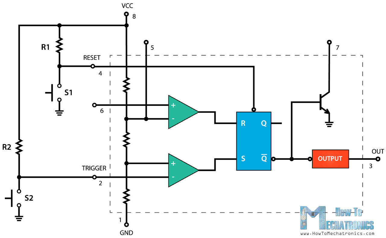
When it comes to understanding the inner workings of electronic circuits, the 555 timer is an essential component. Used in thousands of different applications, this small but mighty chip has become a staple in the world of circuit design. And at the heart of every 555 timer circuit is the ever-important circuit diagram.
So, what exactly is a circuit diagram? In simple terms, it is a visual representation of how a circuit is built and wired. It allows engineers, hobbyists, and students alike to understand the flow of electricity, the connections between components, and the overall functionality of a circuit.
Now, the 555 timer is named after the three 5kΩ resistors used in its internal voltage divider network – a clever trick which enables the timer to produce accurate time intervals independently of supply voltage. This ingenious design, coupled with its eight pins, allows for a variety of configurations, making it an incredibly versatile component for any circuit.
But how does one create a circuit diagram using a 555 timer? First, let's start with the basic schematic symbol for the 555 timer – a rectangle with eight pins sticking out. Each pin has a specific function, such as Trigger, Reset, Output, and Control Voltage, among others.
Next, you need to identify the components you want to use in your circuit, such as resistors, capacitors, and diodes, and determine their placement within the diagram. It's crucial to place the components in the correct order, as any deviation can result in a malfunctioning circuit.
Once you have completed your diagram, it's time to test it out! A fantastic feature of the 555 timer is its ease of use – simply connect the power supply and your chosen input/output devices, and voila! You've successfully created a circuit using a 555 timer.
In conclusion, circuit diagrams using the 555 timer are an essential tool for anyone interested in electronics. Whether you're a professional engineer or a curious hobbyist, understanding this fundamental component and how to incorporate it into your circuits will open the door to endless possibilities. So next time you come across a 555 timer circuit diagram, take a moment to appreciate the small but mighty chip that lies at its core.

555 Timer Ic Working Principle Block Diagram Circuit Schematics

555 Timer Ale Circuit Electrical Engineering Electronics Tools

Flip Flop Using Timer Ic 555 Envirementalb Com

Simple Timer Alarm Circuit Using Ic 555

100 Latest Diy 555 Timer Projects Based On Ne555 Ic

How Can We Make A Timer Of 5 Minutes Using 555 Ic Quora

Time Delay Relay Circuit Using 555 Timer Ic Electronics Projects

Four Way Traffic Lights Circuit Using 555 Timer Ic

30 Minute Timer Circuit Using 555 Ic And 7555

5 20 Minuts Timer Circuit Using Ic 555 Eleccircuit Com

Introduction To The 555 Timer Circuit Basics

Repeating Timer Using Two 555 Ic S

Fire Alarm Circuit Using Ic 555 Timer Thermistor

Pwm Using 555 Timer Circuit And Explanation Ic

10 Best Timer Circuits Using Ic 555 Homemade Circuit Projects

The 555 Timer Based Alarm Circuit With Automatic Reset And Multiple Scientific Diagram

555 Timer

Ic 555 Inverter Circuit Diagram Diy Electronics Projects