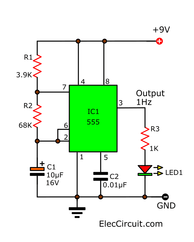
When it comes to understanding electronics and circuitry, the first step is often a visual tool called an IC Schematic Diagram. An IC schematic diagram is a map of how all the different components interact with one another in an electronic circuit system. This visual guide makes it easier for engineers, technicians, and hobbyists to understand complex systems, make modifications, and troubleshoot problems.
At first glance, an IC schematic diagram may seem like an intimidating mess of wires, resistors, capacitors, transistors, switches, and other symbols. However, once you learn to recognize and interpret the different symbols, it’s relatively straightforward to figure out how the different components interact with one another. Each symbol on the diagram corresponds to a real-world component in the circuit. Common symbols include lines indicating wires, circles and boxes representing voltage regulators, arrows and squares for switches, and squiggles for resistors.
Because these diagrams are inherently visual, they can be difficult to describe in words. That’s why computer programs have been designed to generate IC schematic diagrams that can be read by people. Using these tools, it’s easier than ever to quickly and accurately diagram circuit systems.
For the average person, IC schematic diagrams may seem complicated and intimidating. But with some practice and patience, anyone can learn to read and interpret them. Understanding how these diagrams work is a valuable skill to have when it comes to working with electronics – and bodes well for anyone looking to get into the engineering world.

Two Tone Siren Circuit Schematic Using One Ic Diagram And Instructions

Results Page 649 About Electronics Circuit For You Searching Circuits At Next Gr

Ncp3066 Pinout Datasheet Working Circuit Diagram

Simple Timer Alarm Circuit Using Ic 555

How Does Ne555 Timer Circuit Work Datasheet Pinout Eleccircuit Com

Integrated Circuits Design Working Advantages Disadvantages

555 Timer Ic Mosquito Electronic Circuit Electronics Diagram Png 800x600px Area

Digital Integrated Circuits Definition Types Examples Lesson Transcript Study Com
Ne5532 Op Amp Ic Circuit Diagram
What Is 555 Ic Working Principle And Diagram Quora

Schematic Diagram Of The Whole Ic System Scientific

Tja1050 Integrated Circuit Ic Diagram Scientific
Ic 4060 Understanding The Pinout And Their Functions

How To Read A Schematic Learn Sparkfun Com

Build These Simple Alarm Circuits Using Ic 555 Rain Sensor And Light Circuit Bright Hub Engineering

Stereo Audio Amplifier 5w Circuit Using Tea 2025 Ic Envirementalb Com

1 Minute 5 10 And 15 Timer Circuit Diagram Using Ic 555

Tda7388 Circuit 4 Channel Amplifier Diagram Soldering Mind