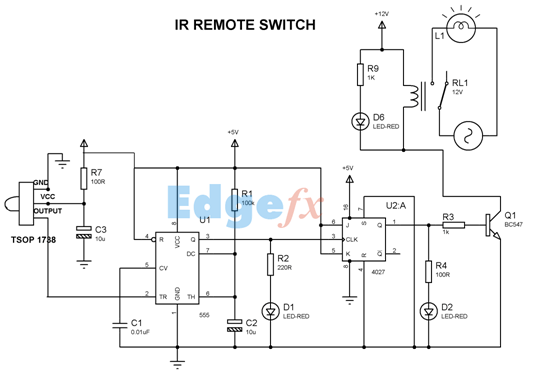
Wireless remote control switch circuit diagrams are a great way to simplify the process of powering your devices. With just one touch of a button, you can instantly select the right electrical settings and turn on exactly the right amount of power for your device. No more fumbling with complex settings and bulky cords - all you need is a single remote control switch.
The concept of wireless remote control is nothing new to modern electronics. Since the early 1950s, remote control technology has become increasingly common in households, from TV remotes to sophisticated garage door openers. However, this same technology has been applied to a variety of circuit diagrams for both commercial and residential purposes. A wireless remote control switch circuit diagram makes it easy to power multiple devices with one simple setup.
The idea is simple: a small receiver is wired into the circuit diagram to receive signals from your remote control. If a particular button is pressed, the receiver sends a signal to the power source, which then responds by turning the appropriate switch on or off. This eliminates the need for multiple switches, as well as reducing the clutter of large electrical cables and cords.
When constructing your own circuit diagram, there are several important things to consider. First, always make sure to use an appropriate power source. Second, be aware that many circuit diagrams are designed to handle specific types of electrical loads, so make sure to check the specifications before connecting your components. Finally, always be sure to use standard safety precautions when working with electricity.
At first glance, wireless remote control switch circuit diagrams may seem confusing, but with a little research, you can quickly understand their basic functions and benefits. Whether you’re powering multiple devices or just one, wireless remote control provides a convenient, cost-effective solution for your electrical needs.

Wireless Switch Circuit Diagram

Remote Controlled Switch Circuit Diagram

2 Simple Infrared Ir Remote Control Circuits Homemade Circuit Projects
433mhz Rf Relay Receiver Wireless Remote Control Switch Led Light Module History Review Aliexpress Er Enjoying E Cigarette Alitools Io

433mhz 12v 4 Channel Relay Module Wireless With Rf Remote Control Switch Without Battery Online At Low In India Electronicscomp Com

120v 220v 380v Ac Motor Forward Reverse Wireless Remote Control Switch

Ir Remote Basics How Tv Work As A Transmitter Applications

How To Build A Simple Fm Wireless Remote Switch Bright Hub Engineering

Complete Circuit Diagram Of Wireless Remote Control Switch Introduction Six Diagrams Electronic Paper

Remote Controlled Switch Circuit For Appliances

Dc 12v 4ch Channel 433mhz Wireless Remote Control Switch 2 Transmitter Receiver For Electric Doors Windows Switches

Simple Rf Remote Control Circuit Without Microcontroller No Need Code

Circuit Diagram Of The Wireless Remote Controller Unit Scientific

Remote Control Switch Circuit Using 4017

Infrared Remote Control Switch Using Cd4027 Ic

Remote Control Light Switch Circuit

Wifi Remote Control Switch Circuit Diagram Electronic Paper

Home Automation Using Ir Remote Control Working Pcb Code Circuit

A Very Simple Ir Remote Control Switch For An Electrical Appliance Embedded Lab

8 Channel Ir Remote Control