Atmega 32u4 based wireless usb mouse part 15 25 internal composition 2311b 2 4g optical schematics protel schematic eastern times technology microsoft bx3 00008 notebook 3000 slate rotational or liasurement using an sensor edn adns2620 ic com 12907 sparkfun electronics how does a computer work explain that stuff wirelessmouse 4ghz shenzhen weiking 046 td 01 adns 2620 interface adnk 2083 nd24 reference design systems arrow 1440up chic tilt wheel circuit diagram and image 02 rf b receiver wude guide fh8811a boards 095208 verbatim xtreme pca21001r dongle instructions manuals overview of history challenges applications under repository circuits 34208 next gr the scientific 3050 navigation with mcu 14core page 8 u400 bluetooth wiring png pngwing what you need to know about s bluetrack eetimes ps2 basic stamp pyruvate的日志 网易博客 make path tracking system xbee arduino 43 49 china v108 ka8 mx8650a dip8l replace paw3205 mx8640 400 500 600 800 1000 default 1200 1600 cpi ultra low power 27 mhz related seekic electronic paper detail necessary components for adapted keyboard full diy project 220020021111 adomax pulse generator 55031 mame cabinet control panel is fundamental difference between laser mice quora

Atmega 32u4 Based Wireless Usb Mouse Part 15 25
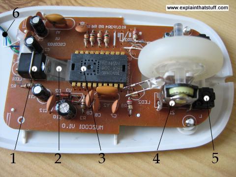
Wireless Mouse Internal Composition
2311b 2 4g Wireless Optical Mouse Schematics Protel Schematic Eastern Times Technology

Microsoft Bx3 00008 Wireless Notebook Optical Mouse 3000 Slate

Rotational Or Liasurement Using An Optical Mouse Sensor Edn

Optical Mouse

Adns2620 Optical Mouse Sensor Ic Com 12907 Sparkfun Electronics

Adns2620 Optical Mouse Sensor Ic Com 12907 Sparkfun Electronics

How Does A Computer Mouse Work Explain That Stuff
Wirelessmouse 2 4ghz Wireless Mouse Schematics Protel Schematic Shenzhen Weiking Technology

How Does A Computer Mouse Work Explain That Stuff

046 Td Usb 01 Adns 2620 Mouse Interface

Adnk 2083 Nd24 Reference Design Optical Systems Arrow Com
1440up Wireless Optical Mouse Schematics Chic Technology

Mouse Sensor

Rotational Or Liasurement Using An Optical Mouse Sensor Edn

Tilt Wheel Mouse Circuit Diagram Schematic And Image 02
Rf 02 B Wireless Optical Mouse Usb Receiver Schematics Shenzhen Wude Electronics
Design Guide

Wireless Mouse Receiver Fh8811a Circuit Boards
Atmega 32u4 based wireless usb mouse part 15 25 internal composition 2311b 2 4g optical schematics protel schematic eastern times technology microsoft bx3 00008 notebook 3000 slate rotational or liasurement using an sensor edn adns2620 ic com 12907 sparkfun electronics how does a computer work explain that stuff wirelessmouse 4ghz shenzhen weiking 046 td 01 adns 2620 interface adnk 2083 nd24 reference design systems arrow 1440up chic tilt wheel circuit diagram and image 02 rf b receiver wude guide fh8811a boards 095208 verbatim xtreme pca21001r dongle instructions manuals overview of history challenges applications under repository circuits 34208 next gr the scientific 3050 navigation with mcu 14core page 8 u400 bluetooth wiring png pngwing what you need to know about s bluetrack eetimes ps2 basic stamp pyruvate的日志 网易博客 make path tracking system xbee arduino 43 49 china v108 ka8 mx8650a dip8l replace paw3205 mx8640 400 500 600 800 1000 default 1200 1600 cpi ultra low power 27 mhz related seekic electronic paper detail necessary components for adapted keyboard full diy project 220020021111 adomax pulse generator 55031 mame cabinet control panel is fundamental difference between laser mice quora
