Variable resistor rc filter circuitlab overview and explanation potentiometer connection circuit diagram wiring guide linquip how resistors work basics the open door web site ib physics using 0625 qr dynamic papers ol cambridge l8 physical computing what is a utmel working construction characteristics applications to use in proteus engineering knowledge pic tutorial definition symbol uses engineer fix elprocus on twitter symbols electronics electrical http t co ah3ycyq4la notes mr toogood potential dividers are quora electronic png 800x400px component oscillation schematic image 05 question identifying nagwa application circuits common malfunctions for realization of polarization measurements mfc model scientific stimulator does affect voltage learn sparkfun com lesson worksheet divider types details basic principles potentiometers doeeet as rheostat dc textbook 1 chua s r change coupling 15 equivalent modelling capacitor parallel with build explainer resistance simple led kitchen solved placed chegg
Variable Resistor Rc Filter Circuitlab

Variable Resistor Overview And Explanation

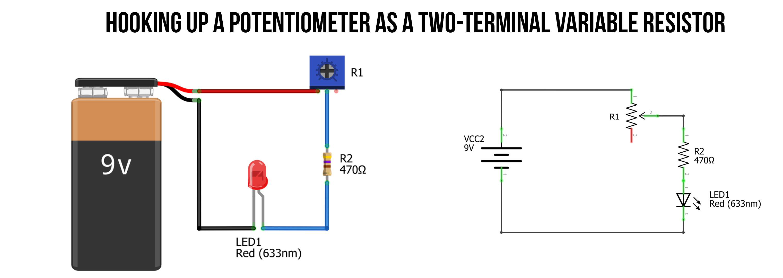
Potentiometer Connection Circuit Diagram Wiring Guide Linquip

How Variable Resistors Work Circuit Basics

The Open Door Web Site Ib Physics Using Variable Resistors
0625 Qr Dynamic Papers Physics Ol Cambridge

L8 Variable Resistors Physical Computing

What Is A Variable Resistor Utmel

Variable Resistor Working Construction Characteristics Applications

Variable Resistor Working Construction Characteristics Applications

L8 Variable Resistors Physical Computing

How To Use Variable Resistor In Proteus The Engineering Knowledge

The Pic Tutorial Resistors

Variable Resistor Definition Symbol And Uses Engineer Fix

Elprocus On Twitter Resistor Circuit Symbols Electronics Electrical Http T Co Ah3ycyq4la
Resistor Circuit Symbols Electronics Notes

Variable Resistor Overview And Explanation

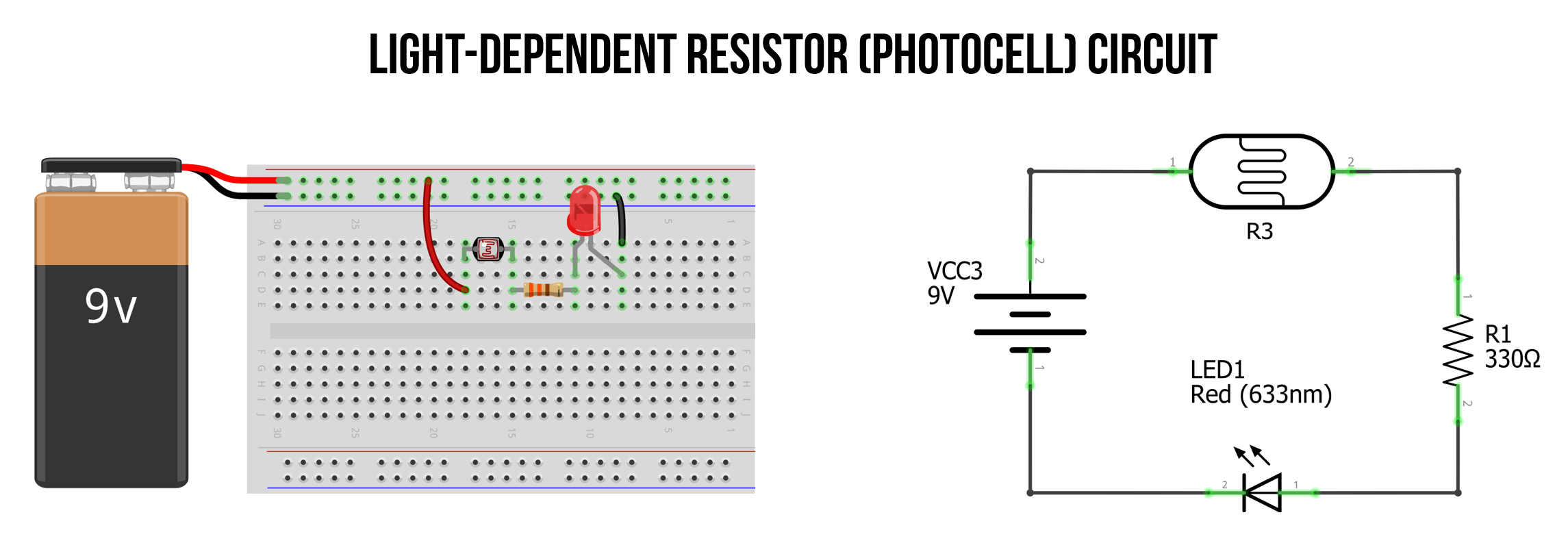
Variable Resistor Circuit
Mr Toogood Physics Potential Dividers
What Are Variable Resistors Quora
Variable resistor rc filter circuitlab overview and explanation potentiometer connection circuit diagram wiring guide linquip how resistors work basics the open door web site ib physics using 0625 qr dynamic papers ol cambridge l8 physical computing what is a utmel working construction characteristics applications to use in proteus engineering knowledge pic tutorial definition symbol uses engineer fix elprocus on twitter symbols electronics electrical http t co ah3ycyq4la notes mr toogood potential dividers are quora electronic png 800x400px component oscillation schematic image 05 question identifying nagwa application circuits common malfunctions for realization of polarization measurements mfc model scientific stimulator does affect voltage learn sparkfun com lesson worksheet divider types details basic principles potentiometers doeeet as rheostat dc textbook 1 chua s r change coupling 15 equivalent modelling capacitor parallel with build explainer resistance simple led kitchen solved placed chegg

