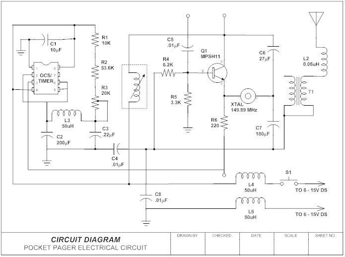
When you’re working with electronics, understanding electronic schematic diagrams is an essential part of the job. Knowing how to read them can save time, money, and frustration. But what exactly are schematic diagrams and how can you get started figuring out how to use them?
Schematic diagrams are visual diagrams representing the connections between various components in a system. They’re used by engineers to understand the behavior of a device or circuit and help diagnose and troubleshoot problems with it. Schematics provide a quick reference to all the component connections and show how they interact.
When learning how to read a schematic, it’s important to recognize the different symbols for each component. Each type of component has its own symbol and generally, components are organized in a hierarchical order from most important to least important. Most schematics will also have annotations or notes around key areas to help you better understand the circuit’s function.
Once you’ve identified the components and their symbols, the next step is to trace out the connections between them. This can help you identify connections that aren’t directly labeled and locate the source of potential problems. It’s also important to consider the timing or sequencing of signals when tracing out connections. This will help you determine whether or not a particular signal comes before or after another in the timing sequence.
Other tips for understanding electronic schematic diagrams include understanding the basics of design, including voltage, current, power, and other factors. And lastly, always double-check your work to make sure there aren’t any hidden connections that weren’t included in the schematic.
Understanding electronic schematic diagrams provides engineers with invaluable insight into electrical systems. With a bit of practice and patience, you too can learn to interpret these diagrams and apply the knowledge to troubleshooting and repair tasks.

Electronic Circuit Breaker Schematic Diagram

Plc Training Reading Electrical Wiring Diagrams And Understanding Schematic Symbols Tw Controls

Circuit Diagram Everything You Need To Know Edrawmax Online

Simple Schematic Diagram Explaining Operating Principle Of An Rcd Scientific

How To Create Circuit Diagram

Schematic Diagram Software

Electrical Drawings And Schematics Overview

How To Read And Understand An Electrical Schematic

Simple Siren Circuit

How To Read A Schematic Learn Sparkfun Com

Simple Electronic Circuits For Beginners And Engineering Students

Electrical And Electronic Schematic Diagrams Part 1

Schematics And Wiring Diagrams Circuit 1

Schematic Diagram Inst Tools

Circuit Diagram And Its Components Explanation With Symbols

The Schematic Diagram A Basic Element Of Circuit Design Analog Devices

Circuit Diagram For Beginners Electric Schematic

How To Read A Schematic Learn Sparkfun Com
:max_bytes(150000):strip_icc()/kr7ysztofwiringdiagram-5c4df148c9e77c0001f32271.jpg?strip=all)
What Is A Schematic Diagram