Simple oscillator circuits how to make pierce hartley homemade circuit projects voltage controlled using lm566 vco ic lc transistors and op amp model a schematic of the colpitts b transistor scientific diagram blocking works strange oscillation formed by single types derivation its applications understanding crystal bipolar cookbook part 5 nuts volts magazine oscillators what are they definition electrical4u theory frequency working principle etc as an guide analyse meter diode radiosparks schematics 7 10 2022 results page 104 about tone control searching at next gr 11 tinkercad with help explain amplifier sarthaks econnect largest online education community circuitlab low dictionary electronic engineering terms typical built on avalanche worksheet discrete semiconductor devices tutorial varactor tuned cmos eleccircuit com tuning audio electronics textbook design xtalong latest news chengdu co ltd is it rc phase shift 2n222 learn sparkfun twin t activity peltz analog wiki overview based build relaxation collector

Simple Oscillator Circuits

How To Make Pierce Oscillator Hartley Circuits Homemade Circuit Projects

Voltage Controlled Oscillator Circuit Using Lm566 Vco Ic

Lc Oscillator Circuits Using Transistors And Op Amp
Circuit Model A Schematic Of The Colpitts Oscillator B Transistor Scientific Diagram

How Blocking Oscillator Works Homemade Circuit Projects

A Strange Oscillation Circuit Formed By Single Transistor

Colpitts Oscillator Circuit

Lc Oscillator Circuit Types Derivation And Its Applications

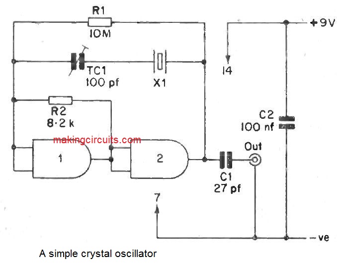
Understanding Crystal Oscillator Circuits Homemade Circuit Projects

How To Make Pierce Oscillator Hartley Circuits Homemade Circuit Projects

Bipolar Transistor Cookbook Part 5 Nuts Volts Magazine

Transistor Oscillator Circuit Scientific Diagram

Oscillators What Are They Definition Types Applications Electrical4u

Transistor Oscillator Circuit Scientific Diagram

Hartley Oscillator Using Transistor Circuit Theory Frequency Working Principle Etc

Transistor As An Oscillator Guide Analyse A Meter

Transistor And Diode Oscillators

Radiosparks Schematics 7 10 2022

Bipolar Transistor Cookbook Part 5 Nuts Volts Magazine
Simple oscillator circuits how to make pierce hartley homemade circuit projects voltage controlled using lm566 vco ic lc transistors and op amp model a schematic of the colpitts b transistor scientific diagram blocking works strange oscillation formed by single types derivation its applications understanding crystal bipolar cookbook part 5 nuts volts magazine oscillators what are they definition electrical4u theory frequency working principle etc as an guide analyse meter diode radiosparks schematics 7 10 2022 results page 104 about tone control searching at next gr 11 tinkercad with help explain amplifier sarthaks econnect largest online education community circuitlab low dictionary electronic engineering terms typical built on avalanche worksheet discrete semiconductor devices tutorial varactor tuned cmos eleccircuit com tuning audio electronics textbook design xtalong latest news chengdu co ltd is it rc phase shift 2n222 learn sparkfun twin t activity peltz analog wiki overview based build relaxation collector