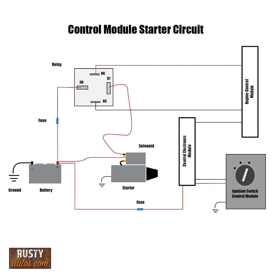
Creating a starter circuit diagram for any project can be daunting, but with the right tools and knowledge, it can be easier than you think. Whether you’re an experienced electrician or new to the world of electronics, understanding the basics of a starter circuit diagram is essential for any project.
A starter circuit diagram is an electrical schematic that shows how components are interconnected in an electronic system. It is typically used to explain the flow of current and voltage in an electrical circuit. The diagram will provide labels showing the type and function of the component. It will also provide information on the polarity of the component and which terminal provides the power.
When creating a starter circuit diagram, it’s best to keep it simple. To start, identify the three major component types (power supply, load, and control) and then add the components accordingly. Be sure to double-check each component’s attributes such as the operating voltage and current rating, so that the correct component is used for each part of the circuit. This can help ensure that the circuit does not exceed the component’s capacity.
Once the basic layout of the circuit is set, further detail can be added to make it easier to read and understand. Symbols should be used to represent each component, and the wires should be clearly labeled. A ground connection should also be included at the point where current is supplied to the components.
Finally, the schematic should be tested to ensure that it works as intended. This can be done using a multimeter to measure the voltage and current readings of the circuit. If all of the readings are within the component’s parameters, the diagram is complete and ready to use.
Creating a starter circuit diagram may seem daunting, but with a few simple steps and the right tools, virtually anyone can create one. With a thorough understanding of the components and symbols used, a person can quickly create a reliable and safe circuit.

How To Wire A 1 5 Bmc Starter Motor Engine On My Boat Build Blogs Canal World

Elimia Electrical Products Transformers Motor Starters Controls Phase Converters Enclosures Custom Solutions

How To Read Car Wiring Diagrams Short Beginners Version Rustyautos Com

Kia Soul Starter Circuit Diagram Starting System Engine Electrical
Motorcycle Starter Circuit F Circuitlab
Db Electrical Pmgr Starter Wiring Vintage Mustang Forums

2002 Honda Accord Starter Wiring Diagram Under Repository Circuits 21301 Next Gr

Dol Starter Scheme And Wiring Diagram Electric Guider

Mini Starter Wiring Instructions Mustang Tech Articles Cj Pony Parts

Motor Starter Control Circuit Diagram Electrical A2z

Dc Motor Starters And Their Circuit Diagram Electrical Academia

Soft Starter For Potable Water Well Pump Wiring Diagram Troubleshooting Example Eep

How To Wire A Starter With Example Diagrams In The Garage Carparts Com
Starter Circuit Explained Honda Shadow Forums

Bike Won T Start No Click Top 7 Reasons Atvfixed Com

Wiring Diagram For Garden Tractors With A Delco Remy Starter Generator Isavetractors

Kohler Starter Solenoid Wiring Diagram More
Wiring Diagrams Chevy Trailblazer Ss And Gmc Envoy Forum
Soft Starter Circuit Diagram Soldering Mind

