What is water level controller types and their working principles uln2004 indicator circuit design electronic project results page 6 about searching circuits at next gr plc program for control ladder logic automatic 2 choice eleccircuit com in depth how sensor works interface it with arduino last minute engineers liquid fluid float tank switch diagram using relay to build an a simple explored bright hub engineering 7 segment led schematic ic diy buzzer electronics projects 2022 8051 microcontroller detailed available its applications bc548 transistor mini device best pump 555 535 camera switching indicators all esp32 tutorial alarm iot based monitoring system make 12 steps pictures home made construction explained full explanation uln2003 images homemade bc547 npn block of the scientific measurement circuits4you submersible uno r3 sensors embedded news tips tutotials esp8266 starters transistors representation proposed controlled pic red page129 sensing state art review performance evaluation low cost sciencedirect

What Is Water Level Controller Types And Their Working Principles

Uln2004 Water Level Indicator Circuit Design Electronic Project

Results Page 6 About Water Searching Circuits At Next Gr

Plc Program For Water Level Control Ladder Logic

Automatic Water Level Controller 2 Circuits Choice Eleccircuit Com

In Depth How Water Level Sensor Works And Interface It With Arduino Last Minute Engineers
Liquid Fluid Water Float Tank Level Switch Circuit Diagram Using Relay

How To Build An Electronic Water Level Controller A Simple Circuit Design Explored Bright Hub Engineering

Liquid Level Sensor Circuit

Water Level Indicator Using 7 Segment Led Electronic Schematic Diagram

Simple Water Level Indicator Circuit Using Logic Ic Circuits Diy

Simple Water Level Indicator With Buzzer Electronics Projects 2022

Water Level Controller Using 8051 Microcontroller

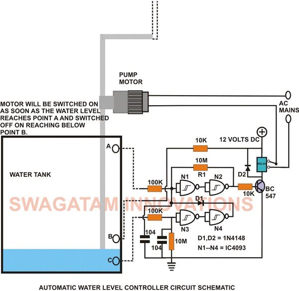
Automatic Water Level Controller Detailed Circuit Diagram Available

Water Level Indicator Circuit Working And Its Applications
Water Level Indicator Using Bc548 Transistor Mini Project

Electronic Water Level Controller Device

What Is Water Level Controller Types And Their Working Principles

Water Level Indicator

Best Automatic Water Pump Controller Circuit Diagram Ic 555
What is water level controller types and their working principles uln2004 indicator circuit design electronic project results page 6 about searching circuits at next gr plc program for control ladder logic automatic 2 choice eleccircuit com in depth how sensor works interface it with arduino last minute engineers liquid fluid float tank switch diagram using relay to build an a simple explored bright hub engineering 7 segment led schematic ic diy buzzer electronics projects 2022 8051 microcontroller detailed available its applications bc548 transistor mini device best pump 555 535 camera switching indicators all esp32 tutorial alarm iot based monitoring system make 12 steps pictures home made construction explained full explanation uln2003 images homemade bc547 npn block of the scientific measurement circuits4you submersible uno r3 sensors embedded news tips tutotials esp8266 starters transistors representation proposed controlled pic red page129 sensing state art review performance evaluation low cost sciencedirect