Inverters are amazing for delivering uninterrupted and reliable power. They’re so important that they’ve become a must-have tool for any home, business, or even industrial setting. But an inverter isn’t just a device you can buy off the shelf. You need to understand how they work in order to build one.
That's why a simple 100w inverter circuit diagram is so important. It gives you the basic building blocks and information you need to construct the device yourself. With a clear cut schematic, it will become clear how to put together all the individual components of the inverter. The goal here is to provide you with the necessary tools to assemble your own inverter and make sure it runs correctly.
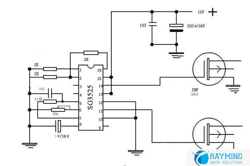
So, what’s involved in a 100w inverter circuit diagram? Basically, it’s a wiring diagram that displays how each component functions in the device. This includes the voltage regulator, rectifier, transformer, and capacitor. The diagram also reveals the correct type of wire to use for the connections. The whole process should be easily followed step by step, ensuring you can get the most out of your inverter.
The importance of a proper diagram is that it allows you to customize the setup however you wish. Plus, a good circuit diagram reduces the risk of overload. With a correctly wired device, you can be sure your inverter is running smoothly and efficiently.
When it comes to building an inverter, the key is to have the right knowledge and resources. A detailed 100w inverter circuit diagram is just that—an indispensable tool that will help make the entire project run more smoothly. Having a reliable, well-made inverter is a great addition to any home or business. So, if you’re ready to take on the challenge, be sure to use a comprehensive diagram before starting. You won’t regret it!

100 Watts Inverter Circuit Working And Applications Envirementalb Com

100 Watts Inverter Circuit Working And Applications Envirementalb Com

Cd4047 Inverter 100 Watt Power Also Why Its Not Good Inverters

500w High Power Inverter Circuit Diagram Mosfet

7 Simple Inverter Circuits For Newcomers

Simple 100w Inverter Using Mosfet Androiderode

100 Watt Power Inverter Circuit Diagram And Pcb

100 Watts Inverter Circuit Working And Applications Envirementalb Com

100w Inverter Circuit Under Repository Circuits 31820 Next Gr

Project Lab Inverter 33 Basic4mcu Com

How To Make A Simple 100w High Frequency Inverter Printed Circuit Board Manufacturing Pcb Assembly Rayming

Inverter Circuit For Soldering Iron Diagram And Instructions

Simple 100 Watt To 500 Inverter Circuit

100w Inverter 12v To 220v Circuit And Products

100 Watt Inverter Circuit Diagram Parts List Design Tips

60w 100w 12vdc To 220vac Inverter Using Transistors Circuits99
Circuitbest Simple Inverter Circuit With Irfz44n Facebook By O Guys Today In This I Will Show You How To Make A Visit My

100 Watts Inverter Circuit Using Cd4047 Irf540

Make This 1kva 1000 Watts Pure Sine Wave Inverter Circuit Homemade Projects
