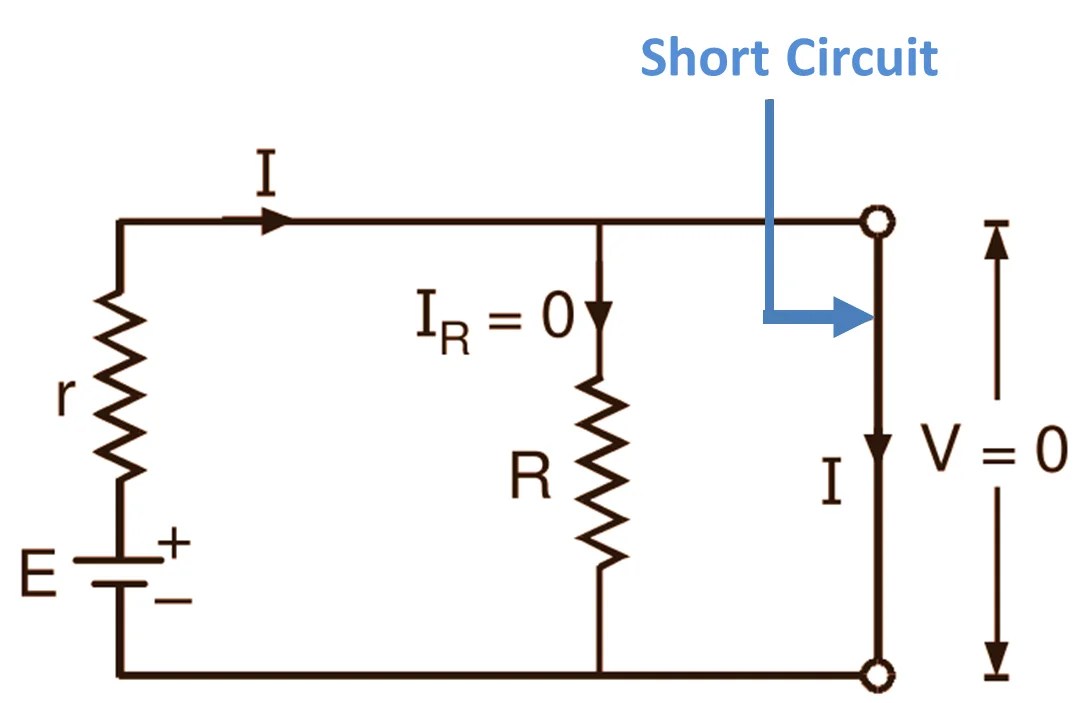
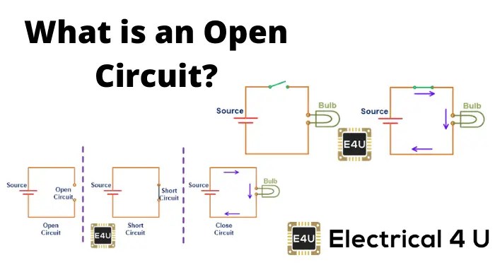
When it comes to designing an electrical circuit, the short circuit schematic is a crucial element. A short circuit is a condition where the current flows from the positive side of the power source to the negative side without passing through the intended load. This can cause significant damage to components and increase electrical hazards.
For any electrician, understanding the fundamentals of short circuit schematics is vital. A basic drawing will show two conductors, typically a line conductor and a neutral conductor, that form a complete circuit. The conductors are connected in series, with each conductor being isolated from the other. The two conductors then connect to a load, such as a light bulb or appliance, to complete the circuit.
The most important aspect of a short circuit schematic is knowing what types of components should be used to ensure safety and proper operation. The main components are a circuit breaker, fuses, and resistors. Circuit breakers sense excessive current and immediately shut off the circuit, while fuses melt if the current flow is too great. Resistors reduce current so the circuit is not overloaded.
Understanding the basics of a short circuit schematic can help electricians determine the best components to use for a particular application. It is also essential to understand how the components are interconnected and how they interact with one another. For example, a resistor may be placed between two conductors to prevent the current from flowing across both conductors at the same time.
Short circuit schematics are a fundamental part of any electrical engineering project. Knowing how to recognize and create appropriate schematics is a key skill in any electrical engineer's toolkit. With the right understanding and knowledge of these schematics, an engineer can ensure their projects are safe and efficient.

Simple Short Circuit Protection Diagram

Short Circuit And Overload
Learn Digilentinc Short Circuits

Short Circuit Definition Diagram Theory Electricalworkbook
What Is A Short Circuit With Diagram Quora

Short Circuits Lesson For Kids Transcript Study Com

Short Circuit Indicator Project
Learn Digilentinc Short Circuits

Short Circuit Protection

Ilized Dc Power Supply With Short Circuit Indication Schematic

Solved Problem 3 35 Points This Relates To Removal Chegg Com

Open Circuit What Is It And How Does Differ To A Short Electrical4u

Electric Circuits Overview Types Complete Open Short Lesson Transcript Study Com
Open Circuit And Short Ultimate Electronics Book

Schematic Diagram Of Three Phase Short Circuit Fault Protection Scientific

What Is A Short Circuit Richmond Home Inspector

Short Circuit Protection For Balanced Supply Rails Eeweb
What Is A Short Circuit With Diagram Quora