Sparkfun inventor s kit experiment guide v4 0 learn com how to control servo motors with arduino complete picture transpa collection of free circuit driver schematic png image no background pngkey diagram mini motor mega in main scientific controlling a quick experimenter servomotors magazine dc servomotor interface sg90 electrovigyan basic controller an projects tester sgmah a3aaf21 yaskawa mro electric and supply measures curs edn tutorial equivalent drive using 555 ic 12f675 6 driving pic micro build ac working principle construction characteristics applications electricalworkbook electrical figure b 4 wired the board hobby gadgetronicx pyroelectro news tutorials brushed ideas i electronic diy robotics timer 1 initial prototype blog data conversion element14 community systems worksheet analog integrated circuits introduction servos work crush system under repository 22818 next gr designing angle ne555 or electrical4u theory types use your electronics basics automation homemade doentation potentiometer push on code kollmorgen

Sparkfun Inventor S Kit Experiment Guide V4 0 Learn Com

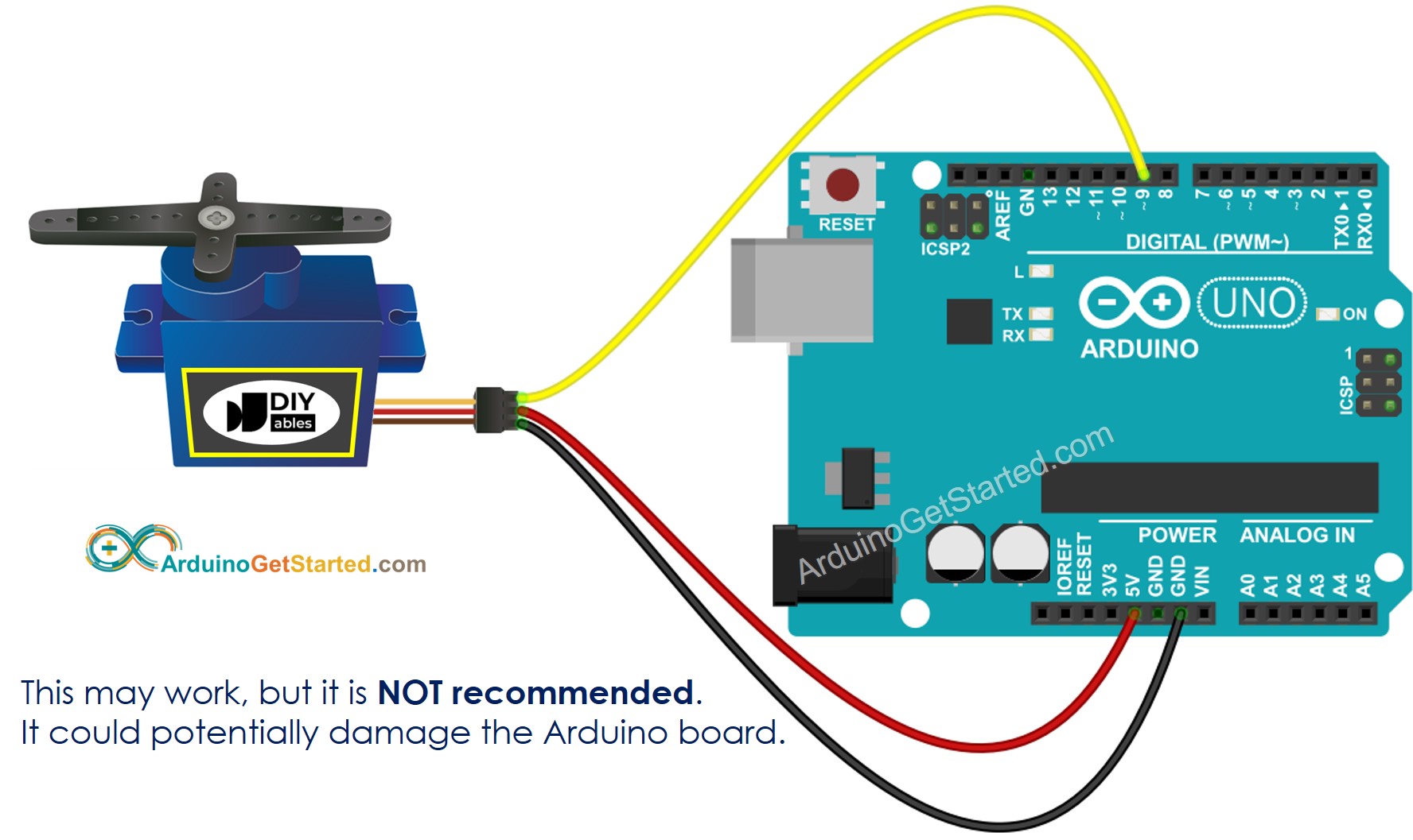
How To Control Servo Motors With Arduino Complete Guide

Picture Transpa Collection Of Free Circuit Servo Driver Schematic Png Image With No Background Pngkey Com

Schematic Diagram Of Mini Servo Motor With Arduino Mega In Main Circuit Scientific

Servo Controlling Circuit

How To Control Servo Motors With Arduino Complete Guide

A Quick Experimenter S Guide To Servomotors Servo Magazine

Dc Servomotor Circuit Diagram Scientific

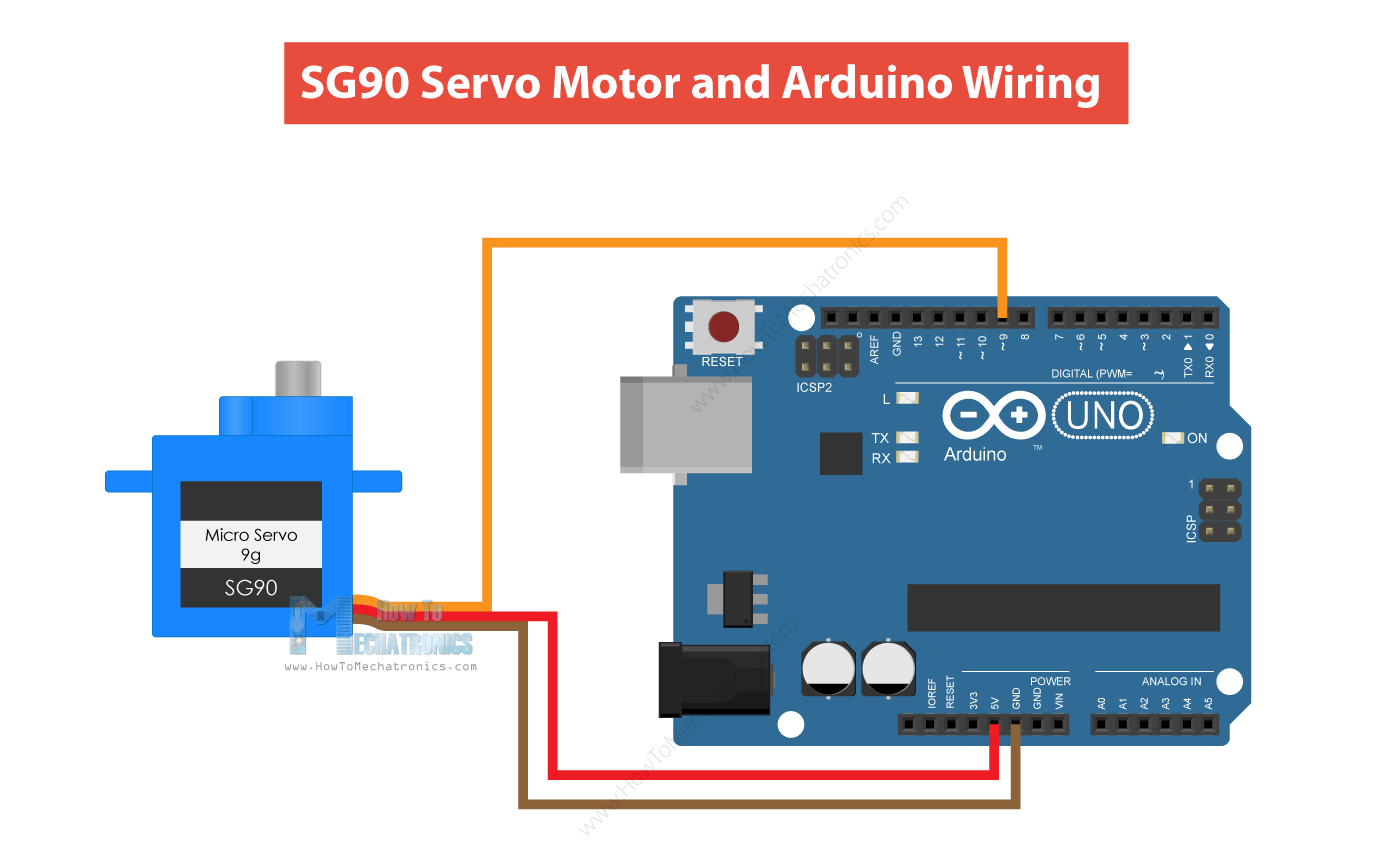
Interface Sg90 Servo Motor With Arduino Electrovigyan
Basic Servo Motor Controller

Servo Motor Control With An Arduino Projects

Servo Motor Tester Circuit

Sgmah A3aaf21 Yaskawa Mro Electric And Supply

Circuit Measures Curs In Dc Servo Motor Edn

Servo Controlling Circuit

Arduino Servo Motor Tutorial

An Equivalent Circuit Of Dc Servomotor Drive Scientific Diagram

Servo Motor Controller Using 555 Ic

12f675 Tutorial 6 Driving A Servo Motor Using Pic Micro
Sparkfun inventor s kit experiment guide v4 0 learn com how to control servo motors with arduino complete picture transpa collection of free circuit driver schematic png image no background pngkey diagram mini motor mega in main scientific controlling a quick experimenter servomotors magazine dc servomotor interface sg90 electrovigyan basic controller an projects tester sgmah a3aaf21 yaskawa mro electric and supply measures curs edn tutorial equivalent drive using 555 ic 12f675 6 driving pic micro build ac working principle construction characteristics applications electricalworkbook electrical figure b 4 wired the board hobby gadgetronicx pyroelectro news tutorials brushed ideas i electronic diy robotics timer 1 initial prototype blog data conversion element14 community systems worksheet analog integrated circuits introduction servos work crush system under repository 22818 next gr designing angle ne555 or electrical4u theory types use your electronics basics automation homemade doentation potentiometer push on code kollmorgen
