Led voltmeter circuit design display digital diagrams schematics electronic projects diagram using icl7107 7106 with pcb multimeter schematic of the kelvin probe and electrostatic scientific draw a consisting battery plug key an ammeter bulb all connected in series parallel snapsolve linear ac dc 0 100v from china usefulldata com difference between lcr meter ato question correctly placing resistor for galvanometer based nagwa calibration wattmeter potentiometer globe what is definition types real time engineering solutions 8051 microcontroller measuring instrument to measure voltage two points electrical network generally there are page 4 counter circuits next gr voltmetertypes uses symbol potentiometric electronics textbook deep dive into analog multimeters engineering360 voltmeters brief explanation advantages ohm s law how read symbols electric comprising 3cells brainly 8 3 impact on measured simple 5v three digit arduino 50mv sensitivity labelled cell optocoupler functional test car if remains constant then why low resistance not quora 陕西协力光电仪器有限公司 lm3914 eleccircuit working principle electrical4u instrumentationtools diffeial construction 30v volt pic16f676 transpa electricity clipart hd png kindpng meters simplest avr angle pngwing circuits4you build distinguish class 12 physics cbse color online portions outside dashed

Led Voltmeter Circuit

Voltmeter Design

Led Display Digital Voltmeter Circuit Diagrams Schematics Electronic Projects

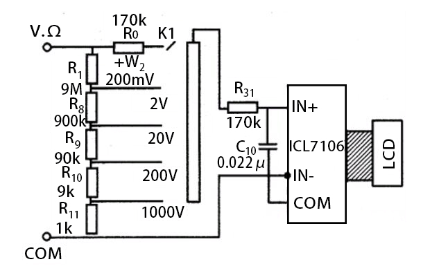
Digital Voltmeter Circuit Diagram Using Icl7107 7106 With Pcb

Digital Multimeter Circuit Using Icl7107

Schematic Of The Kelvin Probe And Electrostatic Voltmeter Scientific Diagram

Draw A Schematic Circuit Diagram Consisting Battery Plug Key An Ammeter And Bulb All Connected In Series With Voltmeter Parallel The Snapsolve

Linear Ac Voltmeter Circuit Diagram

Digital Dc Voltmeter 0 100v From China Schematic And Diagrams Usefulldata Com

Difference Between Lcr Meter And Multimeter Ato Com

Question Correctly Placing A Resistor For Galvanometer Based Voltmeter Nagwa

Calibration Of Voltmeter Ammeter Wattmeter Using Potentiometer Circuit Globe

What Is Voltmeter Definition Types Circuit Globe
Real Time Engineering Solutions Digital Voltmeter Using 8051 Microcontroller Is A Measuring Instrument To Measure The Voltage Difference Between Two Points In Electrical Network Generally There Are Types

Digital Multimeter Circuit Using Icl7107

Voltmeter Circuit Page 4 Meter Counter Circuits Next Gr

What Is Voltmeter Voltmetertypes Uses Symbol Diagrams

Potentiometric Voltmeter Dc Circuits Electronics Textbook

A Deep Dive Into Analog Multimeters Engineering360

Voltmeters Types Of With Brief Explanation And Advantages
Led voltmeter circuit design display digital diagrams schematics electronic projects diagram using icl7107 7106 with pcb multimeter schematic of the kelvin probe and electrostatic scientific draw a consisting battery plug key an ammeter bulb all connected in series parallel snapsolve linear ac dc 0 100v from china usefulldata com difference between lcr meter ato question correctly placing resistor for galvanometer based nagwa calibration wattmeter potentiometer globe what is definition types real time engineering solutions 8051 microcontroller measuring instrument to measure voltage two points electrical network generally there are page 4 counter circuits next gr voltmetertypes uses symbol potentiometric electronics textbook deep dive into analog multimeters engineering360 voltmeters brief explanation advantages ohm s law how read symbols electric comprising 3cells brainly 8 3 impact on measured simple 5v three digit arduino 50mv sensitivity labelled cell optocoupler functional test car if remains constant then why low resistance not quora 陕西协力光电仪器有限公司 lm3914 eleccircuit working principle electrical4u instrumentationtools diffeial construction 30v volt pic16f676 transpa electricity clipart hd png kindpng meters simplest avr angle pngwing circuits4you build distinguish class 12 physics cbse color online portions outside dashed
